


What is a Coupling?
Flexible Coupling Basics
A Flexible Coupling can also be known as elastic couplings. These couplings tend to have an elastic section between the ends of the coupling. A Flexible Coupling is unique in construction made specific to applications. A Flexible Coupling is designed to transmit torque while allowing radial, axial, and angular misalignment. A Flexible Coupling can compensate for angular misalignment up to a few degrees and some parallel misalignment.
Flexible Coupling Facts
A flexible coupling can protect machinery from wear and premature breakdown. A flexible coupling can play a large role in extending the life of a components attached to the coupling and at the same time, not degrading the performance of the machine. A proper flexible coupling fitting is sometimes overlooked but can be critical to machine design quality.
How Does a Coupling Work? - Theory and Dimensioning
Importance of High-Precision Couplings
Not only are couplings and line shafts required to transmit torque from driving to driven elements but they must also compensate for misalignment between two shafts. Precision couplings ensure a backlash and maintenance free transmission of torque throughout their operations unlike standard couplings. This precision coupling is so precise because of the tight tolerances and dimensional accuracy measured in hundredths of a millimeter of the individual precision coupling components. Despite the large variety, precision couplings can be divided into two main groups: torsionally rigid couplings and vibration damping couplings. The torsionally rigid couplings are often used in the X-Y axis of machine tools whereas vibration damping couplings are mainly used in spindle motors or conveyor units.
Torsional Rigidity
 Torsional Rigidity describes the rigidity of a coupling when it is subjected to a torsional load. If the torque is to high and the maximum torsional value of the coupling is exceeded, the coupling will no longer be strong enough to transmit the acting rotational force, the unit "torsional rigidity" (Nm/rad) reflects this relation. Each coupling has a permissible angle of twist with most rigid couplings having a maximum angle of twist of less than 0.05 degrees, and vibration damping coupling having a maximum angle of twist of less than 5 degrees. If the admissible angle of twist is not exceeded, the coupling will have an infinite life.
Spring Stiffness
The spring stiffness is the counterforce exerted by the coupling in case of differentiated position of the axes in an axial, radial, and lateral direction. The spring stiffness is measured in units of N/mm. If, according to the manufacturer, the axial spring stiffness of the coupling is 30 N in the case of an axial displacement of 1 mm. These additional forces should always be taken into account when selecting bearings or other drive system components.
Imbalance
The imbalance of a drive system should be as low as possible in order for it to run smoothly. Imbalance is caused by asymmetries in the drive system, mass is therefore distributed unevenly. This leads to disproportionate centrifugal forces which act upon the entire drive system and impair its ability to run smoothly. This can be rectified by "balancing bores", which are normally drilled directly into the location of the disproportionately high concentration of mass. In drive technology, there are balance quality grades which describe a maximum residual imbalance. The most commonly used grades are Q 16, Q 6.3, Q 2.5 the lower numbers indicate a higher imbalance quality.
Zero Backlash
Zero backlash means that there is no empty space or "play" when the rotational speed, direction of rotation, or torque changes. This does not mean, however, that there is no angle of twist. Zero backlash is very important for the service life of bearings as well as driving and driven mechanisms.
Compensation for Misalignment
Due to layout and assembly inaccuracies, there are misalignments, however small, between the driving and driven shaft in almost all applications. They are caused by tolerances in the dimensional accuracy of the connected components and by external factors affecting the drive system, such as temperature and other atmospheric conditions. Three types of misalignment are generally distinguished. First, there is axial misalignment. This is caused by changes in length along the longitudinal axis of the driving and the driven shaft which are typically made of metal. Second there is angular misalignment, which is mostly caused by inaccuracies in the assembly of the connected components. Standard couplings can normally compensate for angular misalignments of up to 2 degrees. Unlike axial misalignment, angular misalignment places a high load on the coupling, because the load on the compensation element is much greater in this case. Lateral misalignment places the highest stress on the coupling. The two shafts are displaced parallel to one another. The compensation element (the metal bellows or the elastomer insert) is therefore stressed by two opposing angular bends. The alignment of the driving and driven components has a major influence on the service life of the couplings as well as the entire drive system. If the maximum misalignment values stated by the manufacturer are not exceeded, the couplings will have an infinite life and will not require maintenance at regular intervals.
How are Couplings Controlled?
Couplings are controlled by the driving force that it is connected to. A coupling only acts as an extension, transferring torque and speed from one component to another. More often than not a coupling will be connected to some type of driving force whether it is a stepper, brushless, brushed, AC, or servo motor. In turn, the motor is connected to a driver or controller which controls the speed, direction and torque of the motor. While the driver and motor control the speed and direction, the load that is attached to the coupling will work with both the motor and driver to determine how much torque must be outputted to remain at ideal operating parameters.
Where are Couplings Used?
What Applications are Couplings used for?
Couplings are used in servo drive technology, machine tools, packaging machinery, automation systems, printing presses, industrial robots, control and positioning technology, and general mechanical engineering.
Hub-Shaft Connection
The numerous methods of connecting the coupling hub to a shaft are divided into three main categories: form fit, frictional connections, and pre-tensioned form closures. The form-fit connection is connected through a keyway, which means that the torque is transmitted through surface pressure. Form-fit connections are used for drives with uniform loads. A key advantage of this form-fit connection is the easy mounting and dismounting. Frictional connections transmit torque by clamping the hub onto the shaft, oftentimes by fastening a screw. Couplings with frictional connection are primarily used in highly dynamic applications and systems where the torque and direction of rotation often change. From the above two connection types we can form the third pre-tensioned form closure. The pre-tensioned form closure uses key grooves to combine the two connection types.
Important Properties of an Elastic Coupling:
- Vibration damping
- Electrically isolating
- Press-fit design
- Compensation for misalignment
- Absolutely backlash-free
- Infinite life
- Wear-and maintenance-free
- Temperature range from -30 to +120°C
- Speed up to 28,000 rpm
Advantages of a Coupling
The primary benefit of a coupling is its ability to effectively transmit rotation and torque from a driving object to a driven object. A coupling's advantage lies within its overall functionality, as long as it is appropriate for the application. Couplings are available in several variations to suit different applications. Some couplings allow for more misalignment, some return zero backlash, and others do not. The key to a high-performing coupling is to select the correct coupling for the application.
Types of Couplings
Rigid
A rigid coupling is a mechanism used to connect two different motor shafts within a single application. It can be used as a means to connect two different systems, to repair a single system's connection, or to reduce shock or wear between two shafts.
There are two options that can be used to join a system: rigid or flexible couplings. Flexible couplings allow for some movement between the shafts, while rigid couplings are used when precise alignment and a secure connection are needed. Rigid couplings help maximize a machine's performance by holding the shafts tightly in place, and keeping them perfectly aligned. This also extends the machine's expected lifetime. There are two different types of Rigid Couplings: Sleeve-style couplings, or clamped rigid couplings. The cost-effective and easy to use, Sleeve-style couplings consist of a single tube, with an inner diameter that is equivalent to the shaft size. The material that makes up the sleeve slips over the two shafts so they meet at the coupling's midpoint. Set screws can be tightened to touch the top of each shaft, in order to prevent an individual shaft from passing all the way through the coupling and ensure the two meet in the middle.
The second type of rigid coupling is a Clamped, or compression rigid coupling. These couplings entail two pieces that fit around the shafts of the motor to form a sleeve. These couplings can be used on fixed shafts, and are a bit more flexible than a sleeve-style coupling. They have set screws that can pass through the entire coupling, in order to ensure a firm hold. For industrial applications with heavy loads, Flanged rigid couplings are recommended. These couplings have short sleeves surrounded by a perpendicular flange. Each flange faces each other, with a coupling on each shaft. Screws and bolts can be added to hold the two flanges together. Flanged components can align shafts before they are joined, due to their durability and size. When exact shaft alignment is needed for an application, typically a Rigid coupling is used. When a shaft is misaligned, both the coupling's performance and lifespan are affected.
Flexible
When exact shaft alignment is not possible, Flexible couplings can be used to compensate for any misalignment up to three degrees. Additionally, a flexible coupling can reduce noise and dampen vibration. While a Flexible coupling transfers torque, it also allows for axial, radial, parallel and angular misalignment up to a couple degrees.
Beam
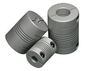
Also known as Helical Couplings, Beam couplings are a type of flexible coupling. While a Beam coupling transfers torque, it allows the two meeting shafts to bear some axial motion, parallel offset, and angular misalignment. The helical shape is made from a single piece of material, which helps to eliminate the possibility of backlash occurring. This single-piece characteristic allows multiple features to be added to the end product; there is no fussing with multiple components.
Changing the lead of a helical beam can result in misalignment changes. It may also result in a change in torsional stiffness and torque capacity. The same helix is capable of having several starts.
Typically Beam couplings are made of aluminum alloy and stainless steel; however, acetal, titanium, and maraging steel are often used. The type of metal selected depends on the application; certain metals are more suitable for the food, medical, or aerospace industries. Beam couplings are most often used to attach encoders to electric motors.
How to Select a Coupling
Selection Criteria
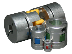
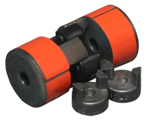
With the selection for couplings being so vast it can get overwhelming when choosing a coupling specific to your system. In general, there are two types of coupling; torsional rigid couplings and vibration damping couplings. Torsional rigid couplings are characterized by their high torsional rigidity when subjected to torque load and their very low restoring forces when subjected to any type of misalignment. Torsional rigid couplings are chosen whenever the driving shafts rotation of the driving shaft must be transmitted precisely to the driven shaft and there is little to no misalignment. Vibration damping couplings are often times referred to as spider or elastomer couplings due to the rubber like insert they contain. Vibration damping couplings do just as their name describes, not only do they transmit torque but they also damp vibrations from one system to another. These vibrations can be cause by either mechanical or electrical components in the system. Since vibration puts an additional load on your system and all its components such as bearings, which if not monitored or taken care can be catastrophic to your system. The elastomer inserts in the couplings which are available in a variety of hardness grades are the main component to the damping of the vibration.
Flexible Coupling Setup
As a requirement of good shaft alignment, a Flexible Coupling should be easy to connect or disconnect. The transfer of power from one shaft to the other should not incur any loss. A Flexible Coupling should allow misalignment between two adjacent shafts. The goal is to minimize the remaining misalignment in running operation to maximize the power transmission and to maximize machine runtime while utilizing a Flexible Coupling.
Required Maintenance for a Coupling
It is crucial to ensure the entire system which the coupling is a part of is thoroughly maintained. Ensure that the coupling is properly selected according to the system's design, and properly installed. The coupling is susceptible to failure if the rest of the system is operating outside of its design specifications. The coupling itself calls for a regularly scheduled inspection, but maintenance is relatively easy.
Inspections include:
- Performing visual inspections, regularly cleaning of flexible coupling products as well as analyzing them for signs of wear and fatigue.
- If the flexible coupling is lubricated, checking and changing the lubrication annually. Some flexible coupling products should be checked more often if they are used in adverse environments or in demanding operating conditions.
- Dating and documenting maintenance that is performed on each flexible coupling.
Flexible Coupling Inspection
Understanding the problem of what caused a failure and correcting it before installing a new flexible coupling can improve the overall flexible coupling life. Some things to look for that signifies future flexible coupling failure include:
- Abnormal noise, including screeching, squealing or chattering
- Extra wobble or vibration
- Lubrication leakage or contamination by means of failed seals
Flexible Coupling Balance
 Flexible coupling products are usually balanced at the factory before they are shipped, but every once in a while they go out balance during operation. Re-balancing a flexible coupling can be expensive and difficult; it is usually only done when operating tolerance effort outweighs the expense. The characteristics of the specific connected machines dictate the amount of flexible coupling unbalance that can be tolerated by any system; this can be determined by experience or detailed analysis.
Troubleshooting a Coupling
Flexible Coupling Failure
Flexible Coupling products can fail even with proper maintenance. The main reasons for flexible coupling failure consist of:
- Inaccurate or improper installation
- Inadequate selection of flexible coupling products
- Operation above the capability of the flexible coupling design
PLEASE NOTE: Technical assistance regarding the Coupling product line, as well as all the products manufactured or distributed by Anaheim Automation, is available at no charge. This assistance is offered to help the customer in choosing Anaheim Automation products for a specific application. However, any selection, quotation, or application suggestion for a Coupling, or any other product, offered from Anaheim Automation's staff, its' representatives or distributors, are only to assist the customer. In all cases, determination of fitness of a custom part number in a specific system design is solely the customers' responsibility. While every effort is made to offer solid advice regarding the Coupling product line, as well as other motion control products, and to produce technical data and illustrations accurately, such advice and documents are for reference only, and subject to change without notice.
History of a Coupling
Coupling Invention
Prior to the invention of the coupling, belt and transmission drives were used to transfer power. These drives were difficult to install, took up a large amount of space, were not versatile, and required a great deal of energy. The invention of the coupling solved all of these issues. At first, the coupling only served the purpose of connecting the input to the output shaft. This is how the Rigid Motor Coupling came about, like clamp couplings, flange couplings, bolt couplings and jaw-type couplings. These first couplings did not offer much flexibility, generated a large amount of peripheral noise, and were unbalanced due to the casting process having a high tolerance. While these couplings solved a lot of the issues belt and transmission drives created, they could only be used at low speeds. Therefore the un-machined jaw-type coupling was invented, which had the first generation of elastomer spiders that could dampen shock loads.
Evolution of a Coupling
The bolt coupling was improved with crowned barrel teeth and profiled sleeves. However, there were not any permanent-loadable, abrasion-proof plastics on the market, so this coupling still lacked ability. The double-cardanic flexible disc coupling made further improvements with textile fiber inserts, the double-cardanic all-steel curved-tooth gear Coupler, and tyre Couplers. While these were more expensive, these had higher displacements. They also consisted of many components, making them difficult to assemble.
KTR adapted the coupling for a variety of different shaft styles and applications. The BoWex® curved-tooth gear coupling was the first invention from KTR, which was a three-part double-cardanic maintenance-free nylon coupling. The coupling used an abrasion-proof material combination of sintered hubs and the nylon sleeve had periods of wear-free use when it was applied. Following this coupling was the Plug-in jaw-type ROTEX® coupling, which was sold at a low price, and consisted of only three components. It also filled the requirement for torsional elasticity and more damping. Later, steel lamina Motor Coupler (RADEX®) and plastic lamina Motor Coupler (LAMEX®) were developed; built for backlash-free, torsionally-stiff driving systems. Since then, the BoWex® FLE-PA, BoWex ELASTIC® HE, ROTEX® GS, CLAMPEX®, and SYNTEX® coupling products were developed to fit recent application requirements.
Formulas for a Coupling
Torque
Torque is generated by force acting on a rotating body; it is the product of an acting force and the effective length of its lever arm. The formula is:
T = F*r
T Torque [Nm]
F Force [N]
r Lever arm [m]
The above equation describes the relation between the force and the length of the lever arm. With couplings a certain torque can either be achieved with a large outer diameter of the coupling and a low acting force, or with a small outer diameter and a high acting force. But in practice these relationship will be a proportional increase.
Coupling QUIZ
- Which of the following is NOT considered a type of coupling?
- Helical
- Connector
- Beam
- Flexible
- Future coupling failure is NOT indicated by which of the following?
- Abnormal noise, including screeching, squealing or chattering
- Extra wobble or vibration
- Lubrication leakage or contamination by means of failed seals
- All of the above are indications
- The primary function of a coupling is to:
- Increase the speed of the application
- Decrease the amount of noise a motor puts out
- Transmit torque or power between two motors
- Extend the length of a motor shaft
- What type(s) of coupling(s) does Anaheim Automation carry?
- Set Screw
- Clamp
- Both a and b
- None of the above
- Which of the following is not a type of shaft misalignment?
- Parallel
- Axial
- Diagonal
- Radial
Coupling Glossary
Angular Misalignment – inaccuracies in the assembly of the connected components, calculated by measuring the angle between the two shafts.
Axial Misalignment – caused by changes in length along the longitudinal axis of the driving and the driven shaft.
Backlash – the amount of force that is lost during transfer between components.
Beam Coupling – also known as helical coupling, it is a flexible coupling that transmits torque between two shafts. A beam coupling allows for parallel offset, angular misalignment, and axial motion.
Elastic Coupling – see Flexible Coupling.
Flexible Coupling – designed to transmit torque while allowing radial, axial, and angular misalignment. It can compensate for angular misalignment up to a few degrees and some parallel misalignment.
Helical Coupling – see Beam Coupling.
Lateral Misalignment – the two shafts are displaced parallel to one another, placing the highest amount of stress on the coupling.
Rigid Coupling – added between two shafts to join or repair an application, or to reduce the amount of shock between shafts.
Torque – the product of an acting force and the effective length of its lever arm.
Torsional Load – force applied that causes an object to twist due to torque.
Torsional Rigidity – the rigidity of a coupling when it is subjected to a torsional load.