We use cookies to make your experience better. To comply with the new e-Privacy directive, we need to ask for your consent to set the cookies. Learn more.
Ball Screw Guide
Ball Screw Guide
Dec 2022
Table of Contents
What Is A Ball Screw?
A ball screw, like all screws, is a rod with a helical groove which translates rotational motion into linear motion.
Why Use A Ball Screw?
Common screws slide on their threads and pull the connecting piece with them. This is how an ACME screw works. This sliding motion is easy to produce but extremely inefficient; around 40% of the input power is transferred to the work piece. To improve on this idea, the sliding contact is replaced with rolling elements. Ball screws utilize ball bearings in the nuts to allow the nut to smoothly roll along the screw. The balls are recirculated to prevent them from falling out of the nut. Current designs of recirculating ball screws typically have a ball screw efficiency greater than 90%.
What Are Ball Screws Used For?
Ball screws are used in applications where high loads must be carried with minimal internal friction. Ball screws provide high efficiency and load capacity, so they are suitable for industrial applications with high static and dynamic loads or in which high torque and thrust are needed. They are also used to provide smooth motion, accuracy, precision, and continuous or high-speed movement.
How Does A Ball Screw Work?
A ball screw works using a highly precise nut with recirculating ball bearings that rotate around a screw thread. When either the screw or nut rotates, the balls travel through the nut, screw, and helical grooves to the ball return system of the nut. They travel in a continuous path, moving from the starting point to the opposite end of the nut and back again. This allows the nut to travel along the length of the screws in a smooth motion.
Anaheim Automation's Ball Screw Offering
Anaheim Automation offers a high-quality line of high-performance ball screws for a wide range of applications. As a distributor of TBI Motion ball screws, Anaheim Automation is sure to have the right ball screw for your application. Choose from a wide range of stroke lengths as well as multiple different preload and accuracy ratings.
TBI Ball Screws: TBI provides Anaheim Automation with a low-cost ball screw assembly solution that saves up to 50% over competitors without compromising quality. Both ground and precision rolled ball screws are available, from 4mm to 80mm in diameter. High precision grades from C0 to C10 are available, delivering up to 7,240kgf of dynamic linear force. Anaheim Automation will cut any ball screw to fit the length requirements of your application. Ball screw support units are also available to supplement your ball screw system.
Physical Properties Of A Ball Screw
The four main components of a ball screw include the ball screw shaft, ball nut, ball bearings, and the seal, each of which are further explained below:
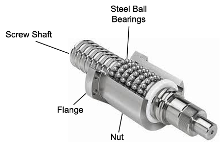
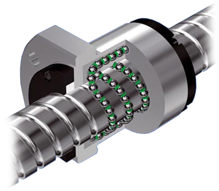
Ball Screw and Nut Assembly
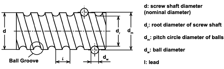
Diagram of a Ball Screw
-
Ball Screw Shaft:
The screw shaft is a long bar of chromium steel that has grooves formed into a helical pattern. This is the main body of a ball screw.-
Ball Groove Design: When forming the groove for a ball screw, it is important to consider the points of contact. The most common groove style is the "gothic arch." This type of groove allows for four points of contact at all times. With four contact points, the ball can be loaded in any direction in that plane.
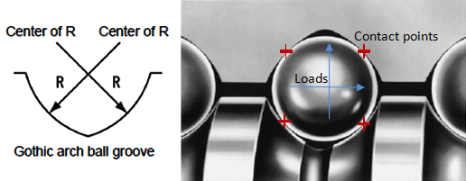
Ball Groove Design
-
Pitch Circle Diameter of Balls: The pitch circle (dm) is measured from the center of the bearing to the center of the bearing on the other side of the screw. This measurement is used for the maximum speed calculations.
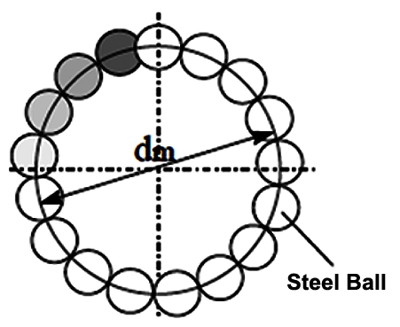
Pitch Circle Diameter
-
Nominal Diameter: The outside diameter of the screw. This measurement is useful for sizing the screw as it is easy to measure.
-
Root Diameter: Diameter from the bottom of the groove to the bottom of the adjacent groove. This is the smallest part of the screw and is important for the critical speed calculation.
-
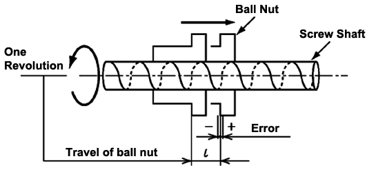
Lead: It is the distance the nut travels in one rotation. The larger the lead, the faster the nut can travel. The lead also determines the vertical maximum payload and the stopping power of the screw. This is because the load angle is steeper for greater leads; the amount of weight it can hold is less.
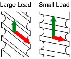
Lead Diameters and Load Angles
-
Ball Diameter: The diameter of the ball bearing that would fit into the groove with a preload of 0. This is used to calculate the diameter of the ball bearing that would give a certain preload. The bigger the balls compared to the nut and screw gap, the higher the preload.
-
-
Ball Nut (Nut and Ball Recirculation):
There are 3 main styles of ball screw nuts, each with a specialty:-
Profile Ball Groove: This is the most common type of ball nut; it is easy to make and provides high-quality, consistent performance. It's simple design makes this nut easy to mass produce and adjust to fit most sizes, leads, and loads. The balls are recirculated by tubes that pick up the bearings and deposit them back into the cycle. The number of rows of balls before they are recirculated is usually between 1.5-3.5 rows to keep the return tube size manageable and make re-balling easier.
Profile Ball Groove
-
Ball Pitch Circle Diameter: This nut has a trimmer profile because it does not use tubes to circulate the ball bearings. Instead, a deflector is used to bump the bearings back into the previous track. This method requires a deflector for every turn, with only one pitch circle per deflector. This design is also inherently better for smaller lead angles because the distance between the grooves is smaller and therefore easier to "jump." This type of nut is more expensive to manufacture because more of the track is internalized and its application is limited by the lead. It is ideal for use in small, space-limited applications with small leads. Because of the recirculation method, there can be only one row per cycle.
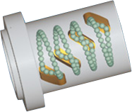
Internal Ball Bearing Circulation
-
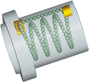
End Cap: These types of nuts are specialized for use with high-lead and multiple-start thread screws. These screws are reserved for these types of nuts because die molds are required to produce the nuts, increasing manufacturing costs. The number of rows per cycle is not limited in this recirculation type. It is normal to have the whole nut recirculated with one cycle per start.
External Ball Bearing Circulation
-
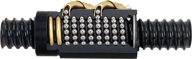
Multiple Starting Threads: A multiple thread screw is typically used in high lead applications to allow for more ball bearings to be in contact with the nut. Multiple threads are only used on high lead screws because there is insufficient physical space to add them on small lead screws. The different colors are the different starts. End caps are used for these ball screws because they utilize less space to recirculate. Another thing to consider with multiple start screws is that the lead and pitch are no longer the same. The lead is equal to the pitch multiplied by the number of starts. For reference, see the diagrams shown below:
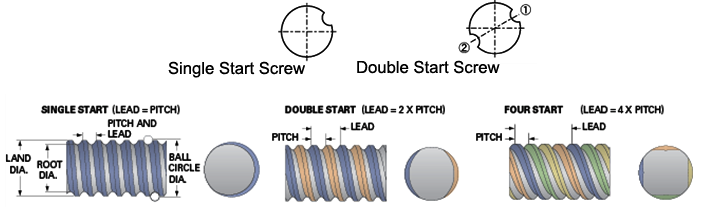
Multiple Starting Threads
-
-
-
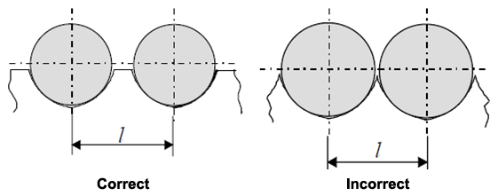
Diameter: The bearing diameter must fit the lead and shaft diameter. If the bearing is too small, there will be too much space between threads; oppositely, if the bearings are too big, the threads will be too close. The crest between the grooves should be flat, but not excessively large.
Ball Bearing Diameters
-
Loading: There is no retainer between the balls as there is with circular bearings, so the balls can become jammed when undesirable ball-on-ball contact is made. This can be reduced by adding spacer balls. Spacer balls are slightly smaller bearings that spin between the load balls, however load capacity will be reduced due to there being fewer load-bearing balls. A synthetic plastic cage has been developed that adds many desirable properties to any recirculating ball bearing application. The plastic cage prevents ball-on-ball contact, reducing friction, preventing jamming, and increasing life. These cages also trap oil and grease, helping to keep the ball well-oiled.
Ball Bearing Diagram
-
-
Seals:
There are both standard and high-performance seals available for use in different environments. All seals prevent foreign matter from entering the space between the nut and ball screw, and some seals are also used for lubricant retention.-
Standard Seal:
Plastic: sed for general or standard ball screws and are of the non-contacting type, blocking debris by means of obstruction
Brush: used for rolled ball screws and are of the contacting type, brushing debris off the track
-
High Performance: Seals that are made specifically for an individual screw nut and lead combination. These seals have a special lip that blocks contaminants, while only slightly increasing operational torque. These seals are used for especially dirty jobs, such as woodworking, welding, and automobile manufacturing.
-
How to Select a Ball Screw
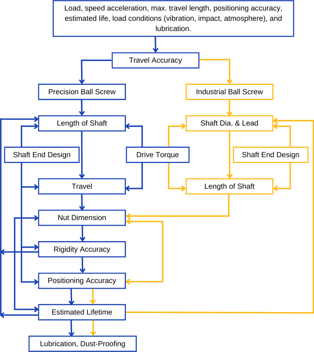
Ball Screw Selection Flow Chart
Accuracy
According to the standard of JIS, we classify our lead accuracy using the four main ratings of "E, e, e300 and e2π". Below, shown in figures 1.3.1 ~ 1.3.3, the definitions and tolerances are specified. To test the accumulated travel deviations for grade C7 and C10 balls screws, the tolerance will be chosen from a random 300mm length of the screw and evaluated to see if it qualifies with the e300 of Table 3.
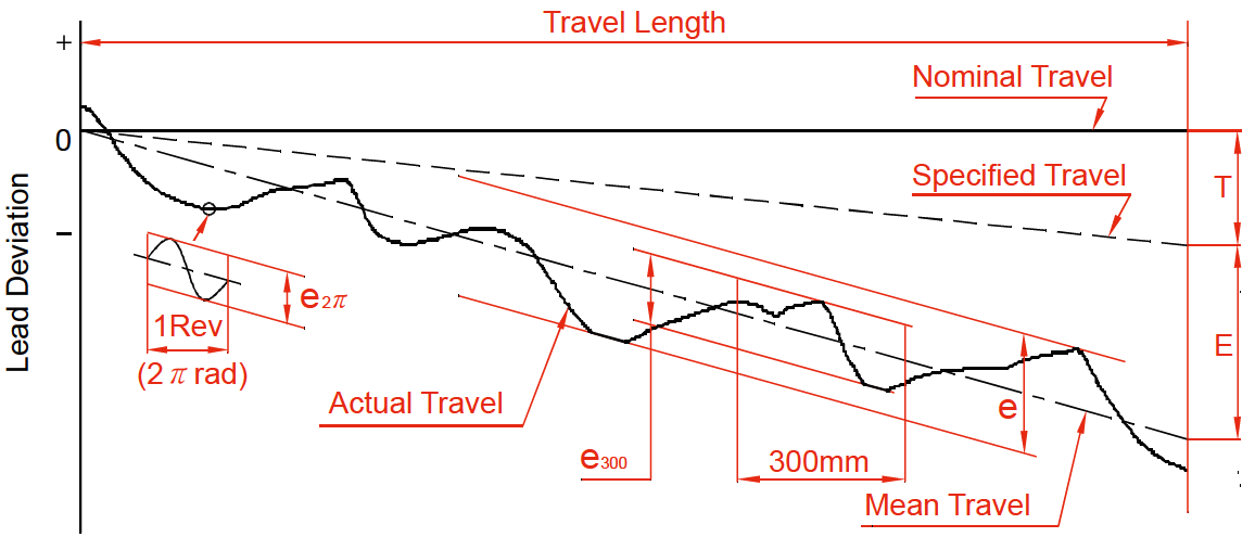
Fig. 1.3.1 Lead Accuracy Diagram
| Terms | Reference | Definition | Allowable |
|---|---|---|---|
| Travel Compensation | T |
Travel compensation is the difference between specified and nominal travel in the useful travel region. A slightly smaller value compared with nominal travel is often selected by users to compensate for the expected elongation caused by temperature rise or external load. Therefore, "T" is usually a negative value. *Note: If no compensation is required, specified travel is the same as nominal travel. |
|
| Actual Travel | Actual travel is the axial displacement of the nut relative to the screw shaft. |
||
| Mean Travel |
Mean travel is the linear best fit line of the actual travel. This is obtained by the least squares method. This line represents the tendency of actual travel. |
||
| Mean Travel Deviation | E |
Mean travel deviation is the difference between mean travel and specified travel within travel length. |
Table 2 |
| Travel Variations | e | Travel variations refer to the coverage of 2 lines drawn parallel to the mean travel. |
Table 2 |
| e300 | Maximum width of variation within the total travel length. | Table 3 | |
| e2π |
Actual width of variation for the length of 300mm taken anywhere within the travel length. Wobble error, actual width of variation for one revolution (2π radian). |
Table 3 |
Table 1: Terms and Definitions
| Grade | C5 | C7 | C10 | |||
|---|---|---|---|---|---|---|
|
Travel Length (mm)
|
Over | Incl. | ±E | e | e300 | e300 |
| - | 100 | 18 | 18 | ±50/300mm | ±210/300mm | |
| 100 | 200 | 20 | 18 | |||
| 200 | 315 | 23 | 18 | |||
| 315 | 400 | 25 | 20 | |||
| 400 | 500 | 27 | 20 | |||
| 500 | 630 | 30 | 23 | |||
| 630 | 800 | 35 | 25 | |||
| 800 | 1000 | 40 | 27 | |||
| 1000 | 1250 | 46 | 30 | |||
| 1250 | 1600 | 54 | 35 | |||
| 1600 | 2000 | 65 | 40 | |||
| 2000 | 2500 | 77 | 46 | |||
| 2500 | 3150 | 93 | 54 | |||
| 3150 | 4000 | 115 | 65 | |||
| 4000 | 5000 | 140 | 77 | |||
| 5000 | 6300 | 170 | 93 | |||
| 6300 | 8000 | 210 | 115 | |||
| 8000 | 10000 | 260 | 140 | |||
| 10000 | 12500 | 320 | 170 | |||
Table 2: Mean Travel Deviation (±E) and Travel Variation (e) [Units in μm]
| Grade | C5 | C7 | C10 |
|---|---|---|---|
| e300 | 18 | 50 | 210 |
| e2π | 8 | - | - |
Table 3: Variation per 300mm (e300) and Wobble Error (e2π) [Units in μm]
Axial play of TBI MOTION’s precision ball screws vs preload value is shown in the table below:
| Grade | P0 | P1 | P2 | P3 | P4 |
|---|---|---|---|---|---|
| Axial Play | Yes | No | No | No | No |
| Preload | No | No | Light | Medium | Heavy |
Table 4: Classification of Axial Play
Excessive preload increases the friction torque and generates heat, which will reduce the life expectancy of the ball screw. However, insufficient preload will reduce stiffness and increase the possibility of lost motion. TBI MOTION recommends that the preload applied on CNC machine tools be no heavier than 8% of the dynamic load, and for industrial automation X-Y tables it should not exceed 5%.
| Model No. | Spring Force (Kg) Single Nut | Spring Force (Kg) Double Nut |
|---|---|---|
| 1605 | 0.1~0.3 | 0.3~0.6 |
| 2005 | 0.1~0.3 | 0.3~0.6 |
| 2505 | 0.2~0.5 | 0.3~0.6 |
| 3205 | 0.2~0.5 | 0.5~0.8 |
| 4005 | 0.2~0.5 | 0.5~0.8 |
| 2510 | 0.2~0.5 | 0.5~0.8 |
| 3210 | 0.3~0.6 | 0.5~0.8 |
| 4010 | 0.3~0.6 | 0.5~0.8 |
| 5010 | 0.3~0.6 | 0.8~1.2 |
| 6310 | 0.6~1.0 | 0.8~1.2 |
| 8010 | 0.6~1.0 | 0.8~1.2 |
Table 5: Reference Spring Force of (P2)
| Nominal Diameter | Rolled Ball Screw Clearance in the Axial Direction (max.) | Ground Ball Screw Clearance in the Axial Direction (max.) |
|---|---|---|
| Ø04~ Ø14 miniature ball screw | 0.05 | 0.015 |
| Ø15~ Ø40 medium ball screw | 0.08 | 0.025 |
| Ø50~ Ø100 large ball screw | 0.12 | 0.05 |
Table 6: Axial Play (P0) Clearance in the Axial Direction of Rolled & Ground Ball Screws [Units in μm]
Definition of Mounting Accuracy and Tolerance on Ball Screw:
The main items of the mounting accuracy of ball screws are listed below.
- Run-out of the supporting part of the screw shaft to the screw groove
- Concentricity of the mounting portion of the shaft to the adjacent ground portion of the screw shaft.
- Perpendicularity of the shoulders to the adjacent ground portion of the screw shaft.
- Perpendicularity of the nut flange to the axis of the screw shaft.
- Concentricity of the ball nut diameter to the outer diameter of the screw groove.
- Parallelism of the mounting surface of a ball nut to the screw groove.
- Total run-out of the screw shaft to the center axis of the screw shaft.
All TBI MOTION ball screws are manufactured, inspected, and guaranteed to be within specifications.
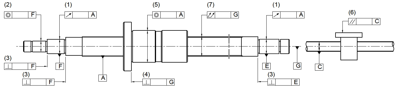
Fig. 1.3.2 Mounting Accuracy and Tolerance
The diagram below specifies the types of preload torque generated by rotating a preloaded ball screw:
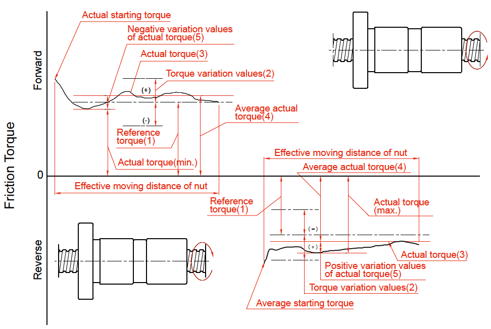
Fig 1.3.3 Preload Torque Descriptions
| Reference Torque (kgf*cm) | Effective Threading Length (mm) | |||||||||||
|---|---|---|---|---|---|---|---|---|---|---|---|---|
| Below 4000 | 4000 ~ 10,000 | |||||||||||
| Slenderness 1: below 40 | Slenderness 1:40 ~ 1:60 | - | ||||||||||
| Grade | Grade | Grade | ||||||||||
| Over | Incl | C0 | C1 | C2, C3 | C5 | C0 | C1 | C2, C3 | C5 | C1 | C2, C3 | C5 |
| 2 | 4 | ±35% | ±40% | ±45% | ±55% | ±45% | ±45% | ±55% | ±65% | - | - | - |
| 4 | 6 | ±25% | ±30% | ±35% | ±45% | ±38% | ±38% | ±45% | ±50% | - | - | - |
| 6 | 10 | ±20% | ±25% | ±30% | ±35% | ±30% | ±30% | ±35% | ±40% | - | ±40% | ±45% |
| 10 | 25 | ±15% | ±20% | ±25% | ±30% | ±25% | ±25% | ±30% | ±35% | - | ±35% | ±40% |
| 25 | 63 | ±10% | ±15% | ±20% | ±25% | ±20% | ±20% | ±25% | ±30% | - | ±30% | ±35% |
| 63 | 100 | - | - | ±15% | ±20% | - | - | ±20% | ±25% | - | ±25% | ±30% |
| Notes: "Slenderness" is the value of dividing the outside diameter of the screw shaft by the threading length. For reference torque less than 2 kgf * cm, TBI Motion specifications will apply. | ||||||||||||
Table 7: Permissible Ranges of Torque Variation Rates
Calculation of Reference Torque Tp
The equation for computing reference torque of the ball screws is given in the following:

Where:


Measurement Conditions
The measurement condition as indicated in Fig 1.3.4, the preload dynamic torque will be the multiplication of F (the force to make the nut stay still during rotating the screw) and L (the arm of force).

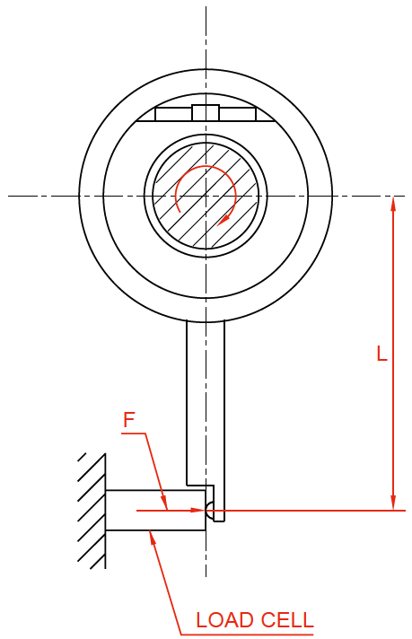
Fig. 1.3.4 How to Measure Preload Dynamic Torque
Screw Shaft Design
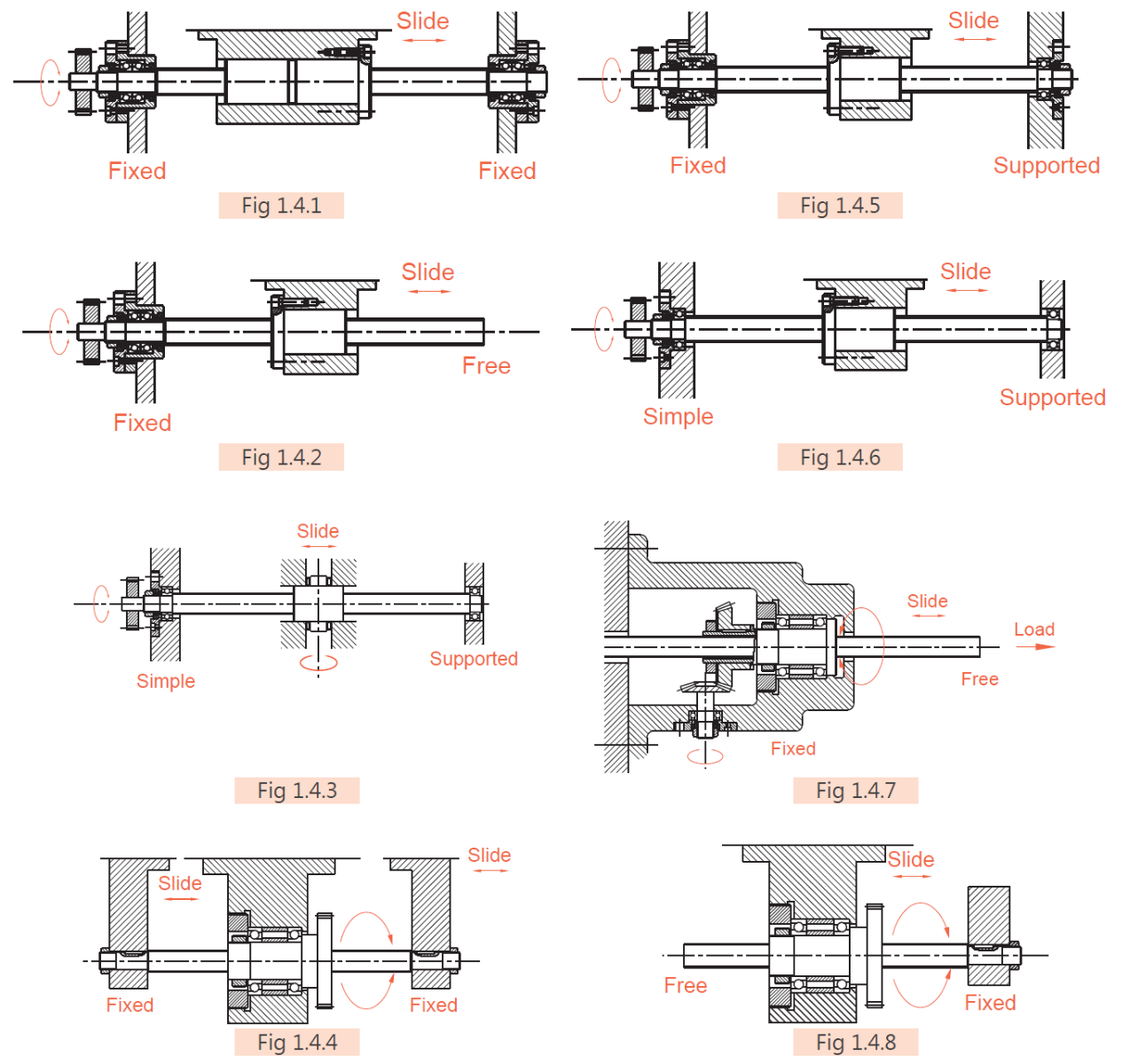
Mounting Methods
It is important to consider the mounting method (Fig 1.4.1~1.4.8) during the selection of ball screw. If you have any special requirements related to the mounting method, please consult Anaheim Automation.
Mounting Screw and Nut

Mounting Method for Common Types of Machinery
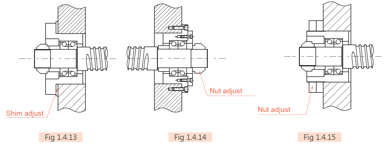
Mounting Method for Bearing in a Given Pretension
Allowable Load of Axial Direction
Buckling Load
The safety of the screw shaft against buckling needs to be checked when the shaft is expected to receive high axial loads. Fig 1.4.16 shows a diagram which summarizes the allowable axial compressive load for buckling for each nominal outside diameter of screw shaft.

Where:
α = Safety factor α = 0.5
E: Vertical elastic modules (E = 2.1 ∙ 104 kgf/mm2)
I: Minimum secondary moment of screw shaft sectional area

dr: Screw shaft root diameter (mm)
L: Mounting distance (mm)
m ∙ N: Coefficient determined from mounting method of ball screw
Floated – Floated m = 5.1 (N = 1)
Fixed – Floated m = 10.2 (N = 2)
Fixed – Fixed m = 20.3 (N = 4)
Fixed – Free m = 1.3 (N = 1/4)
Critical Speed
Dangerous Speeds
To prevent the screw's from obtaining its natural resonance frequency which will occurs at the screws critical speed and will cause the ball screw to wobble and become unstable, it is necessary to limit the rotational speed of the screw to 80% or lower of the Critical Speed. For more details regarding allowable rotational speed classified though screw diameter, please refer to Fig 1.4.17.
dm ∙ n value
The allowable rotational speed is also regulated by the Dm x N value (Dm: diameter of central circle of steel ball, N: Revolution speed in rpm) which expresses the peripheral speed.
Generally, for precision (accuracy grade C7 to C0): Dm x N ≤ 70,000
For general industry (C10): Dm x N ≤ 50,000
If your requirement for the product will exceed these limitations, please contact Anaheim Automation to discuss the solutions for the ideal product.
*When ε (also called the slenderness ratio), the ratio of screw length to the shaft diameter, has exceeded 70, please contact Anaheim Automation for special arrangement for production.

Where
α: Safety factor (α = 0.8)
E: Verticle elastic modules (E = 2.1 ∙ 104kgf/mm2)
I: Minimum secondary torque of axial section plane

dr: Screw shaft root diameter (mm)
g: Acceleration of gravity (g = 9.8 ∙ 103 mm/s2)
γ: Density (γ = 7.8 ∙ 10-6 kgf/mm3)
A: Screw shaft sectional area (A = πdr2/4mm2)
L: Mounting distance (mm)
f, λ: Coefficient determined from the ball screw mounting method
Floated – Floated f = 9.7 (λ = π)
Fixed – Floated f = 15.1 (λ = 3.927)
Fixed – Fixed f = 21.9 (λ = 4.730)
Fixed – Free f = 3.4 (λ = 1.875)
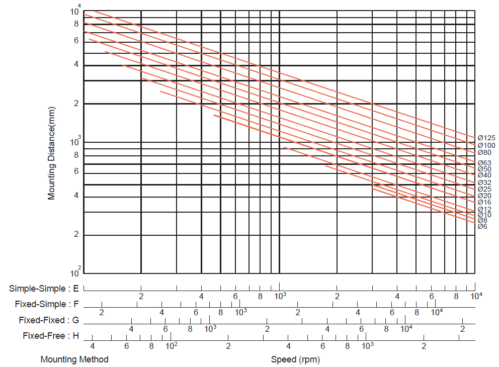
Fig. 1.4.17 Buckling Load vs Nominal Diameter and Length
Driving Torque
Driving torque TS (of the transmission shaft)


Acceleration TG


Load torque Tp


 (
( )
)


 (
( )
)
Preload torque TD


Friction torque TF


The friction torque of the bracing shaft will be affected by the volume of lubrication oil. Be careful with excessive and overtight end seals, as this may lead to unexpected friction torque or temperature rise.
[For reference] Moment of inertia of load (refer to Table 1.5.1)


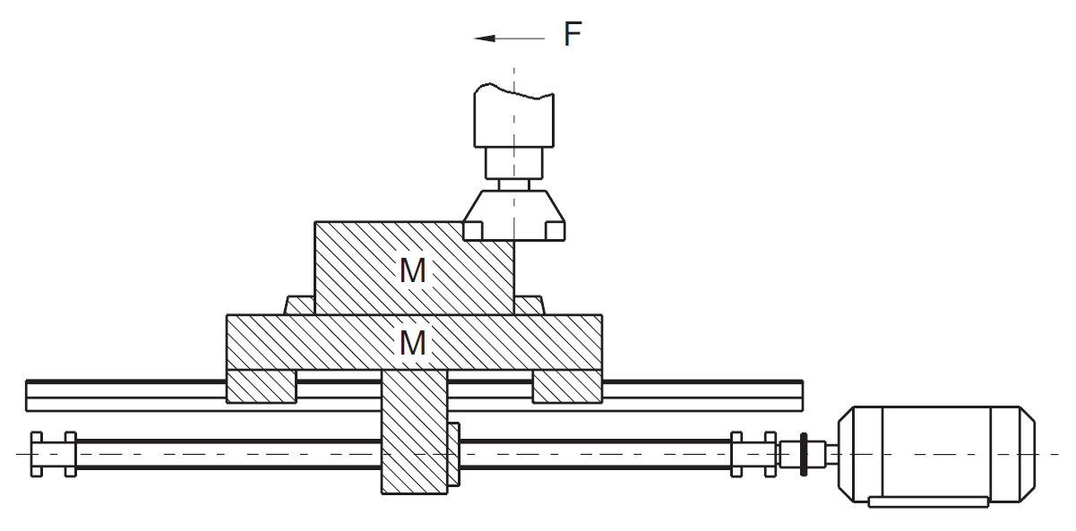
Fig. 1.5.1 Moment of Inertia Load
| Moment of Inertia Converted from Motor Shaft | J |
|---|---|
| Cylinder Load |

|
| Linearly travelling object |

|
| Unit |

|
| Moment of Inertia During Deceleration |

|
ρ: Density
 where
where

where
L: Cylinder length (m)
D: Cylinder diameter(m)
M: Mass of the linear motion part (kg)
V: Velocity of the linear moving object (m/min)
NM: Motor shaft revolutions (min-1)
P: The moving magnitude of the linearly moving object per rotation of the motor (m)
Nl: Rotations in longitudinal moving direction (min-1)
Jl: Moment of inertia in load direction
JM: Moment of inertia in motor direction
Nut Design
Selection of Nut
| Circulation Type | Model | Characteristic | |
|---|---|---|---|
| Single Nut | Double Nut | ||
| Internal circulation | SFM, SFNI, SFK, SFNU, BSH | DFM |
|
| External circulation | SFV, XSV, BSH | DFV |
|
| End-caps circulation | SFY, SFH | DFS |
|
Nut Types
U, I, M - Type Nut:
In these types of nuts, by using an internal circulator to make the balls pass over the crest diagonally, the balls will return to the starting point. Normally, one roll of the balls will fit with one circulation of the nut. As figure 1.6.1 shows, these types of nuts need least one side to allow the balls to traverse from one thread to another leaving small gaps in the threads, which is applicable for smaller shaft diameters.
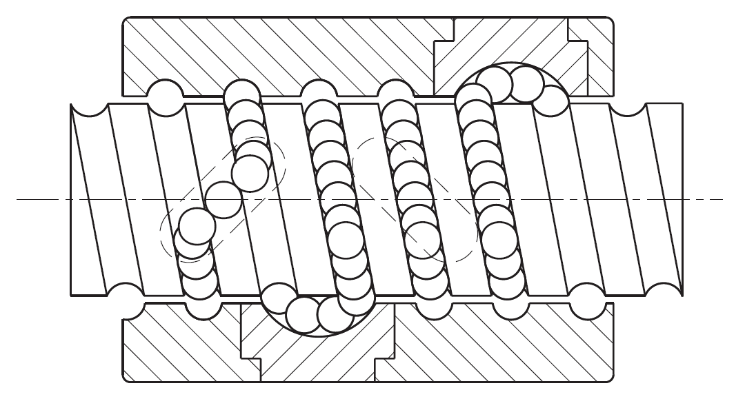
Fig. 1.6.1 U, I, and M Type Nuts
K - Type Nut:
With similar circulation as that of the I-type, but the circulation takes place in key slots with identical angles for smooth circulation. (see Fig 1.6.2)
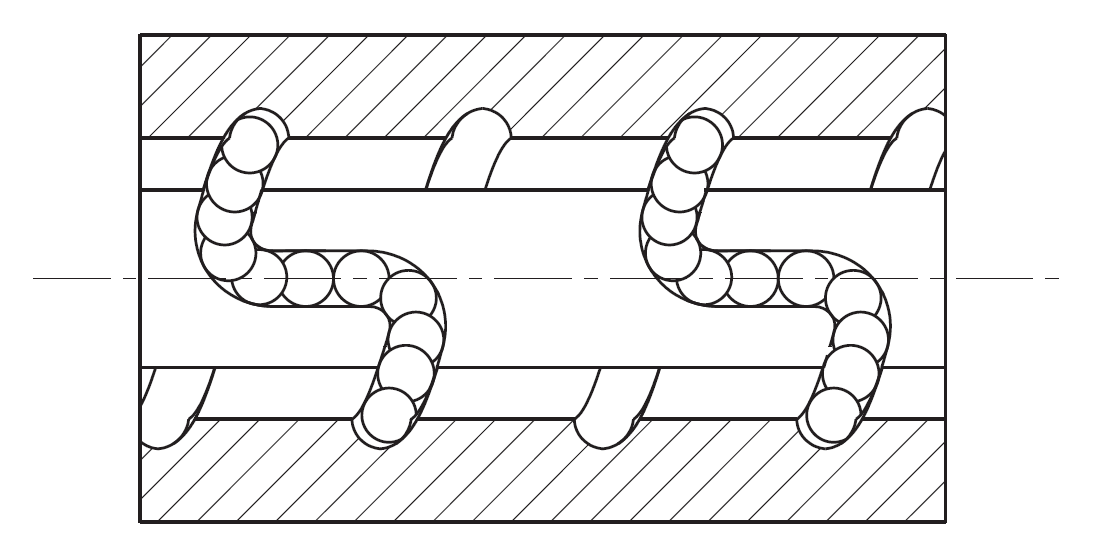
Fig. 1.6.2 K Type Nuts
V - Type Nut:
Using outer circulation, the special design of circulator allows the balls to roll along the thread direction. This type of circulation increases the smoothness and at the same time decreases the collisions between balls. This nut is suitable for high speed and heavy loading.
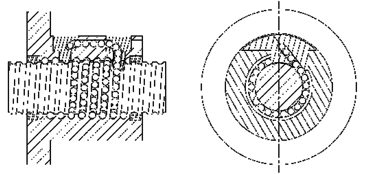
Fig. 1.6.3 V Type Nuts
Y, H - Type Nut:
By using thin and flexible dust caps on both sides of the circulation returns, the performance of wiping/cleaning the balls has been enhanced. The enhancement of this circulation structure increases both the rigidity and speed of the ball screw.
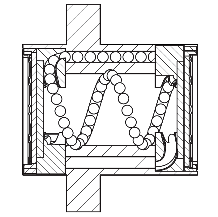
Fig. 1.6.4 Y and H Type Nuts
Rigidity
Excessively weak rigidity of the screw's peripheral structure is one of the primary causes that result in lost motion. Therefore, in order to achieve excellent position accuracy for the precision machines such as NC working machines and etc, axial rigidity balance as well as torsional rigidity for the parts at various portions of the transmission screw have to be taken into consideration at time of designing.
Static Rigidity K:
The axial elastic deformation and rigidity of the transmission screw system can be determined by the formula below.

P: Axial load (kgf) borne by the transmission screw system
e: Axial flexural displacement (mm)

KS: Axial rigidity of screw shaft (1)
KN: Axial rigidity of nut (2)
KB: Axial rigidity of support shaft (3)
KH: Axial rigidity of installation (4)
-
Axial rigidity KS and displacement δS

P: Axial load (kgf)


-
Axial rigidity KN and displacement δN of nuts
(a) In case of single nut


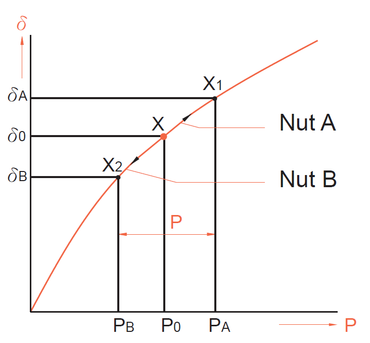
Fig. 1.7.3 Single vs Double Nut Rigidity
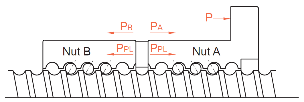
Fig. 1.7.2 Preloaded Double Nut
As bearing weight of preload (PPL) exert, there will be approximately three times of axial loading (P). To eliminate the preload of nut b, please set the bearing weight of preload (PPL) under 1/3 of the maximum axial load weight. Take 0.25 Ca as maximum load weight of preload. When the displacement under the preload which equals to three times of the bearing load of the axial direction, the value will be 1/2 of single nut's displacement.
- Axial rigidity KB and displacement δB of support shaft
-
Look into the nut and bearing mounting part’s axial direction, the rigidity KH and displacement δH should aware of the requirement of high rigidity on mounting portion during the initial machine development.

Positioning Accuracy
Among the factors that cause feed accuracy errors, lead accuracy and feed system rigidity are the key points for review, while other factors such as heat deformation due to temperature rise as well as assembly accuracy for the guiding surface, etc. should also be considered.
| Application | Accuracy Grade | ||||||||
|---|---|---|---|---|---|---|---|---|---|
| C0 | C1 | C2 | C3 | C5 | C7 | C10 | |||
|
NC Machine Tools
|
Lathe | X | ✓ | ✓ | ✓ | ✓ | ✓ | ✓ | |
| Y | ✓ | ✓ | ✓ | ||||||
| Milling Machine or Boring Machine | XY | ✓ | ✓ | ✓ | ✓ | ✓ | |||
| Z | ✓ | ✓ | ✓ | ✓ | |||||
| Machine Center | XY | ✓ | ✓ | ✓ | ✓ | ||||
| Z | ✓ | ✓ | ✓ | ||||||
| Jig Borer | X | ✓ | ✓ | ||||||
| Y | ✓ | ✓ | |||||||
| Drilling Machine | XY | ✓ | ✓ | ✓ | |||||
| Z | ✓ | ✓ | |||||||
| Grinding Machine | X | ✓ | ✓ | ✓ | ✓ | ✓ | ✓ | ||
| Z | ✓ | ✓ | ✓ | ✓ | ✓ | ||||
| Electro-Discharge Machine (EDM) | XY | ✓ | ✓ | ✓ | ✓ | ✓ | |||
| Z | ✓ | ✓ | ✓ | ✓ | |||||
| Wire Cut (EDM) | Y | ✓ | ✓ | ✓ | |||||
| UV | ✓ | ✓ | ✓ | ✓ | |||||
| Punching Press | XY | ✓ | ✓ | ✓ | |||||
| Laser Cutting Machine | XY | ✓ | ✓ | ||||||
| Z | ✓ | ✓ | |||||||
| Woodworking Machine | ✓ | ✓ | ✓ | ✓ | |||||
| Machines of General/Special Use | ✓ | ✓ | ✓ | ✓ | ✓ | ||||
|
Semiconductor
|
Explosure Equipments | ✓ | ✓ | ||||||
| Chemical Treatment | ✓ | ✓ | ✓ | ✓ | |||||
| Wire Bonder | ✓ | ✓ | ✓ | ||||||
| Prober | ✓ | ✓ | ✓ | ✓ | |||||
| Inserter | ✓ | ✓ | ✓ | ✓ | |||||
| PCB Driller | ✓ | ✓ | ✓ | ✓ | ✓ | ||||
|
Industrial
|
Orthogonal Type | As'sy | ✓ | ✓ | ✓ | ✓ | |||
| Others | ✓ | ✓ | ✓ | ||||||
| Multi-Joints Type | As'sy | ✓ | ✓ | ✓ | |||||
| Others | ✓ | ✓ | ✓ | ||||||
| SCARA Type | ✓ | ✓ | ✓ | ✓ | |||||
| Machines for Steel Molding | ✓ | ✓ | ✓ | ||||||
| Injection Molding Machines | ✓ | ✓ | ✓ | ||||||
| Three-Dimensional Measuring Machines | ✓ | ✓ | ✓ | ||||||
| Business Machines | ✓ | ✓ | ✓ | ||||||
| Pattern Image Machines | ✓ | ✓ | |||||||
|
Nuclear
|
Rod Control | ✓ | ✓ | ✓ | |||||
| Mechanical Snubber | ✓ | ✓ | |||||||
| Aircraft | ✓ | ✓ | |||||||
Table 8: Ball Screw Applications Based on Accuracy Grade
Life Design
Even when the ball screw is operated under the correct conditions, inevitable wear and tear on the components will lead to eventual failure. The service lifetime of the ball screw typically ends when delamination occurs and the accuracy of the device begins to suffer.
Basic Static Load Rating Coa
The basic load rating is an axial static load which will produce a permanent deformation at contact points of the steel balls to ball grooves equal to 0.01% of ball diameter.
Basic Dynamic Load Rating Ca
The basic dynamic load rating is an axial load which allows 90% of a group of identical ball screws (rotated under the same conditions) to rotate without flaking for 106 revolutions. This basic dynamic load rating is shown in the table of dimensions.

Fatigue Life
Average Load Pe
-
When axial load keeps changing, calculate the average load for the equivalent fatigue life under different load conditions. See Table 9.
Axial Load (kgf) Rotating Speed (min-1) Time (%) P1 n1 t1 P2 n2 t2 - - - - - - - - - Pn nn tn 
Usage Life in Hours (h) Working Machines 20,000 General Industrial Machines 10,000 Automatic Control Machines 15,000 Measurement Machines 15,000 Table 9: Estimated Service Life in Different Applications

Pmax: Maximum axial load (kgf)
Pmin: Minimum axial load (kgf)
-
When load changes according to sine curve (see Fig. 1.9.2)


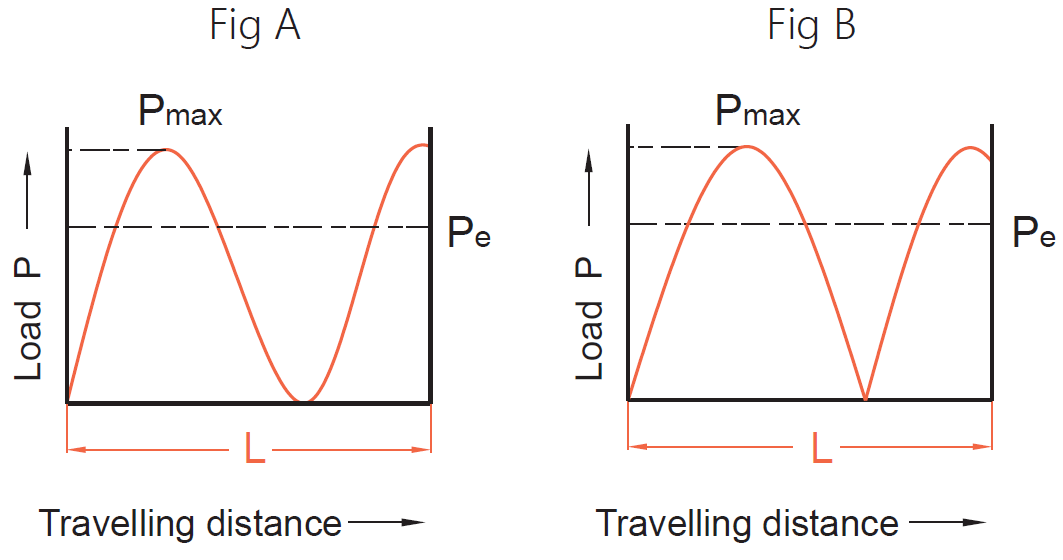
Fig. 1.9.2 Load-Travel Distance Sine Curves
Calculation of Life Expectancy
The fatigue life is generally expressed by the number of revolutions. The total rotation hours or total travel distance may also be used to express service life. The fatigue life is calculated as follows:


Where:
L: rated fatigue life (rev)
Ls: life in travel distance (km)
Pa: axial load (kgf)
fw: load coefficient (required coefficient to operate)
Lt: life in hours (h)
Ca: basic dynamic load rating (kgf)
n: rotating speed (rpm)
l: lead (mm)
| Vibration & Impact | Velocity (V) | fw |
|---|---|---|
| Minor | V ≤ 2.5m/s (very low) | 1~1.2 |
| Light | 0.25 < V ≤ 1m/s (low) | 1.2~1.5 |
| Moderate | 1 < V ≤ 2m/s (medium) | 1.5~2 |
| Heavy | V > 2m/s (high) | 2~3.5 |
Table 1.9.2 Load Factor (fw)
| Usage | Operation | fs |
|---|---|---|
| Machine Tool | Normal Operation | 1.0~1.3 |
| Operation with Impact & Vibration | 2.0~3.0 | |
| Industrial Machine | Normal Operation | 1.0~1.5 |
| Operation with Impact & Vibration | 2.5~7.0 |
Table 1.9.3 Factor of Safety (fs)
Basic Dynamic Load Rating Ca

Basic Static Load Rating Coa

What Is Accuracy?
Accuracy is a crucial component in ball screw operation, as ball screws are utilized primarily for their precision and accuracy retention. Lead error and mounting error are two calculated error parameters that are important to consider in your ball screw application.
-
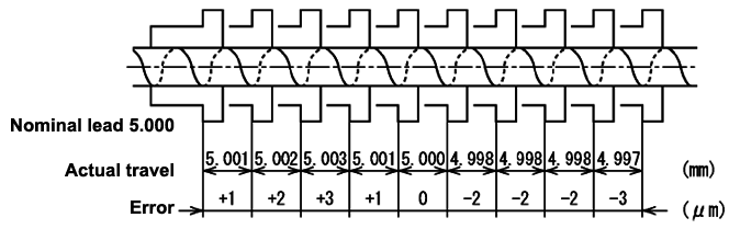
Lead Error: Lead error is defined in two ways: the difference between the expected length (L) and the actual length (L±e), and the sum of all the e's (∑ e=E). For example, if L is 5mm and e±0.05mm, the possible length could be 4.995-5.005mm.
Travel of a Ball Nut
Actual Travel
- Mounting Error: Mounting errors are caused by the way the screw is supported and the installation of the ball nut. The three most likely mounting errors are bearing misalignment, coupling misalignment, and nut misalignment. Mounting errors can create noise, shorten component life, and cause positioning errors.
What Is Preload?
Preload is a load that is placed on a part (bolts, screws, bearings, etc) before its operating load is applied. This load causes some elastic deformation that improves performance. Elastic deformation is a change in shape that is fully reversible, like squishing a rubber ball. In the case of ball screws, the preload is on the interface of the nut and screw. The ball bearings and both the nut and screw grooves are all "squished" together.
This "squishing" eliminates backlash and reduces deflection. Backlash is the amount of lost motion caused by looseness in the drive train which can cause placement errors. The preload creates a tight fit for the nut, eliminating backlash. The increased stiffness is a result of the phenomenon where as a piece of steel is loaded elastically, it becomes increasingly hard to deform it. The preload eliminates the possibility of "easy" deformation; a greater amount of force is required.
There are a few different ways to add a preload:
- Pick a ball that is bigger than the groove
- Pick a nut that is smaller than the screw
- Pick a screw that is bigger than the nut
- Use 2 nuts and insert a wedge
- Use 2 nuts and insert a spring
- Offset grooves inside the nut
Ball Screw Assembly:
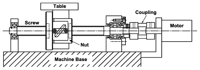
A ball screw must be supported so that the shaft can be rotated. Usually this involves roller bearings and holding brackets. Some longer screws require additional support for critical speed and bending restraints. End machining may be required to fit into the bearing or connect to the motor. Connecting to the motor requires a coupling and the appropriate machining. In order for the nut to translate accurately, it must be restrained by a table and support rails. In the end, the assembly should look something like the ball screw diagram below.
Ball Screw Assembly
What Type Of Lubrication Do Ball Screws Use?
Ball screws can use either grease or oil for lubrication. It is recommended to use grease for most normal applications. This is because grease does not require any special lubricating system and less of it is needed than oil. Oil is most often used for high-speed applications.
History Of Ball Screws
There have been attempts to replace sliding friction screws with rolling friction screws since the 19th century. However, because of the limited level of manufacturing and technology, the first practical application of ball screws was by General Motors, who used ball screws for their steering columns. Since then, the technology surrounding ball screws has advanced rapidly. This rapid advance has led to mass production and use in CNC machines, automated manufacturing, and medical devices. With superior accuracy, repeatability, and high efficiencies, ball screws are the best way to translate rotational motion into linear motion.
Ball Screw Applications
Ball screws are used in motion control but require bearing supports and motor couplings to work effectively. By using ball screws in conjunction with linear stages, we are able to produce stable linear translation for many applications. For this reason, ball screws are used in a broad range of industries ranging from garage door openers to CNC machines and MRI table sliders.
Ball Screw Applications
Ball screws are not typically used in applications requiring oscillating motions less than that of a ball diameter. This type of motion removes the lubrication layer and leads to increased error. This can be worked around by using smaller ball screws and/or special grease.
Ball Screw Advantages And Disadvantages
Ball Screw Advantages And Disadvantages
Ball Screw vs. Lead Screw
The difference between a ball screw and lead screw is that a ball screw has ball bearings that eliminate the friction between the nut and screw while lead screws do not. The screw and nut on ball screws have helical grooves that allow ball bearings to roll along the screw and recirculate. Lead screws have deeper helical threads and a mating nut. Because lead screws do not contain ball bearings, the nut and screw shaft slide against each other, creating friction.
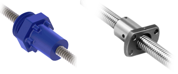
Lead Screw (left), Ball Screw (right)
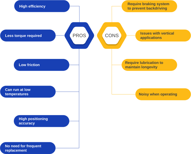
Compared to ball screws, lead screws are less expensive, less noisy, do not require a braking system, and are more suitable for vertical applications. However, they are also less efficient and require greater torque, have high friction, run at hotter temperatures, are less suited to high speed applications and long cycle times, and due to wear caused by friction they need to be replaced more often.
Ball Screw vs. Lead Screw Accuracy
Ball screws have higher positioning accuracy than do lead screws due to their lower backlash. The ball nut can be preloaded by being split into two pieces that are separated by a spring, forcing the balls into the channel and removing the backlash from the system. Thus, ball screws are better suited for applications requiring smooth motion, accuracy, and high precision.
Estimated Lifetime Of A Ball Screw
Ball screws have very low friction coefficients, which is the key to both their accuracy and longevity. The actual life is determined by load, speed, lead and screw size. Common values for the lifetime of a ball screw are 20,000 hours, and 50,000km or 5 years.
Required Maintenance For A Ball Screw
Most ball screws require a certain degree of regular maintenance, but some specialty ball screws do not require any maintenance! Make sure that the rails are free of contaminates such as water, dirt, dust and debris. The nut should also be lubricated using either oil or grease. Grease offers lower overall performance but is much more convenient, cheaper to use, and easier to maintain than oil (which requires a circulation system).