We use cookies to make your experience better. To comply with the new e-Privacy directive, we need to ask for your consent to set the cookies. Learn more.
Brushless DC Motor Guide
Feb 2023
Table of Contents
What is a Brushless DC Motor?
A Brushless DC Motor (also known as a BLDC motor), is a synchronous electric motor powered by a direct current. As the name implies, the brushless DC motor does not operate using brushes, but rather, with a controller via electronic commutation.
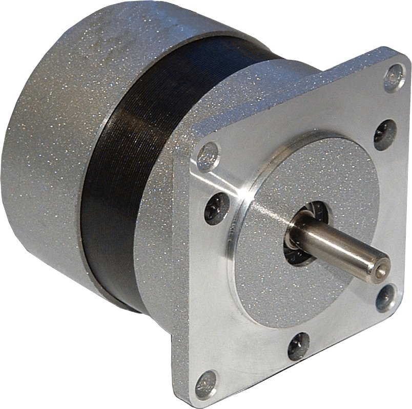
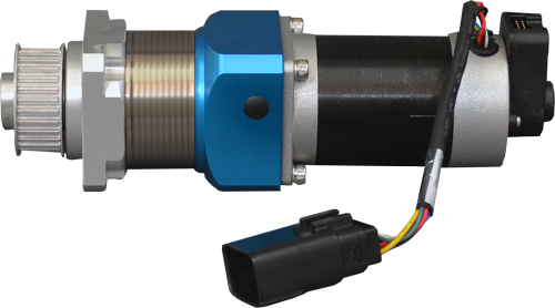
BLWS23 Series Brushless DC Motor
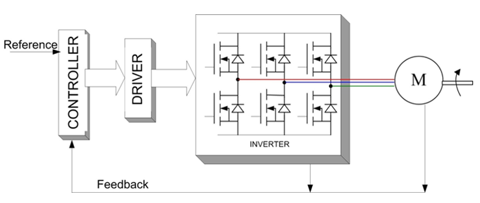
Block Diagram: Brushless Motor System
How Do Brushless DC Motors Work?
A brushless DC motor is operated by means of an electronic six-step commutation system. Unlike its brush DC motor counterparts, the brushless DC motor does not contain any carbon brushes. Instead, the electromagnets within the motor remain stationary along with the armature while the encased permanent magnets rotate, generating torque. The brushless DC motor is synchronous; both the stator and the magnetic field generate the same frequency, therefore avoiding any type of "slip" most induction motors exhibit.
What is Six-Step Commutation?
Six-step commutation is a cost-effective means of electronic commutation due to the simple and relatively inexpensive feedback and drive devices. In six-step commutation, only two out of the three brushless DC motor windings are used at a time. Steps are equivalent to 60 electrical degrees, so six steps make a full, 360 degree rotation. One full 360 degree loop is able to control the current due to the fact that there is only one current path. Six-step commutation is typically useful in applications requiring high speed and commutation frequencies. A six-step brushless DC motor usually has lower torque efficiency than a sine-wave commutated motor.
How is a Brushless DC Motor Controlled?
An electronic Brushless DC Controller (also known as a "driver" or "electronic speed controller") replaces the mechanical commutation system used by a brush DC motor, and is required by most brushless DC motors to operate. In a brushless DC motor controller, either a Hall effect sensor or back EMF (electromotive force) is used to identify the position of the rotor. The rotor speed is controlled by pulse-width modulation, or PWM. Understanding the orientation of the rotor is crucial to operating the brushless DC motor.
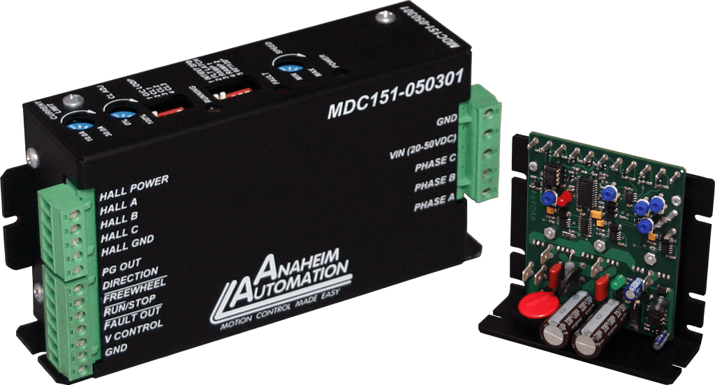
Brushless Motor Driver and Speed Controller
What are Hall Effect Sensors?
There are three Hall effect sensors within the brushless DC motor that help detect the position of the rotor. A Hall effect sensor is a switch designed to detect a magnetic field and output a logic level. Hall effect sensors are typically used in place of a mechanical commutator and brushes. The sensors are spaced at a certain angle to provide sensor feedback of the magnetic field in order to properly commutate the three motor phases. They are also used in speed detection and positioning.
What is Back EMF?
Back EMF, also known as the counter-electromotive force, is caused by a changing electromagnetic field in the armature windings of a brushless DC motor. In other words, the voltage is developed in an inductor by an alternating or pulsating current caused by the rotating magnetic field. You can take advantage of the back EMF to commutate the motor windings. This method is commonly used to measure the position and speed of the brushless DC motor indirectly. A disadvantage of back EMF is that it is very small and difficult to measure at low speeds, resulting in inefficient operation. Once the motor is stationary, no back EMF is generated, so the start-up is affected by operating without back EMF feedback.
Precautions should be taken to ensure back EMF does not cause buildup of energy on the power rails of the driver. If the voltage increases to above the ratings, the motor components will be damaged.
What is PWM?
PWM, or pulse-width modulation, can be used to control the average voltage across the windings, which in turn controls the speed of the brushless DC motor. A PWM controller switches the input voltage on and off and varies the duty cycle. The applied power is controlled by varying the width of the applied pulses. The speed is controlled by changing the timing of the pulses. The longer the pulse is “on,” the faster the motor will rotate.
Optical Encoders can also be added to the brushless DC motor, allowing both direction and speed to be determined. More precise applications may use optical encoders with a third index signal to determine pulse per revolution.
BLDC Motor Driver Hook-Up Tutorial
Physical Properties of a Brushless DC Motor
The brushless DC motor consists of a rotating rotor, Neodymium Iron Boron (NdFeB) magnets, and a stator. Brushless DC motors are considered to be an "inside-out" version of a brush DC motor; the commutator and brushes are nonexistent, and the windings are located externally, connected to the controller. There are typically two different construction types for the brushless DC motor: inrunner and outrunner configurations. The inrunner configuration consists of three stator windings located around the rotor, with permanent magnets as a part of the rotor. The outrunner has a reversed relationship between the magnets and the coils. The permanent magnets rotate inside a suspended rotor surrounding the core of the brushless DC motor.
Exploded view – Brushless Motor
Internally, a 3-phase motor can be configured to a "wye" or "delta" configuration. The primary advantage to the "wye" configuration, also known as the "star" configuration, is that the phase-to-neutral voltage is equal in all three legs. The arrangement is a parallel circuit in a shape of the letter Y, where all windings are connected at a central point, and power is applied to the remaining windings.

"Wye" Configurations
The delta configuration creates a triangle-like figure, making it a series circuit. This configuration applies power to each of the connections.

Delta Configurations
How to Select a Brushless DC Motor
Selecting the appropriate brushless DC motor requires knowing the requirements of the application, such as torque, speed, size, power, length, etc. While determining which brushless DC motor best fits the requirements, the controller must be considered as well, as this goes hand in hand with the operation of the brushless DC motor.
Lastly, environment is important to consider. Applications requiring a harsh, damp environment may require motors with specific IP ratings. For more detailed information on this subject, see the section on environmental considerations.
Brushless DC Motor Applications
The cost of the brushless DC motor has declined since its introduction, due to advancements in materials and design. This decrease in price, coupled with the many advantages it has over the brush DC motor, makes the brushless DC motor a popular component in many different applications. Applications that utilize the brushless DC motor include, but are not limited to:
BLDC Motor Industries and Applications
Advantages & Disadvantages of Brushless DC Motors
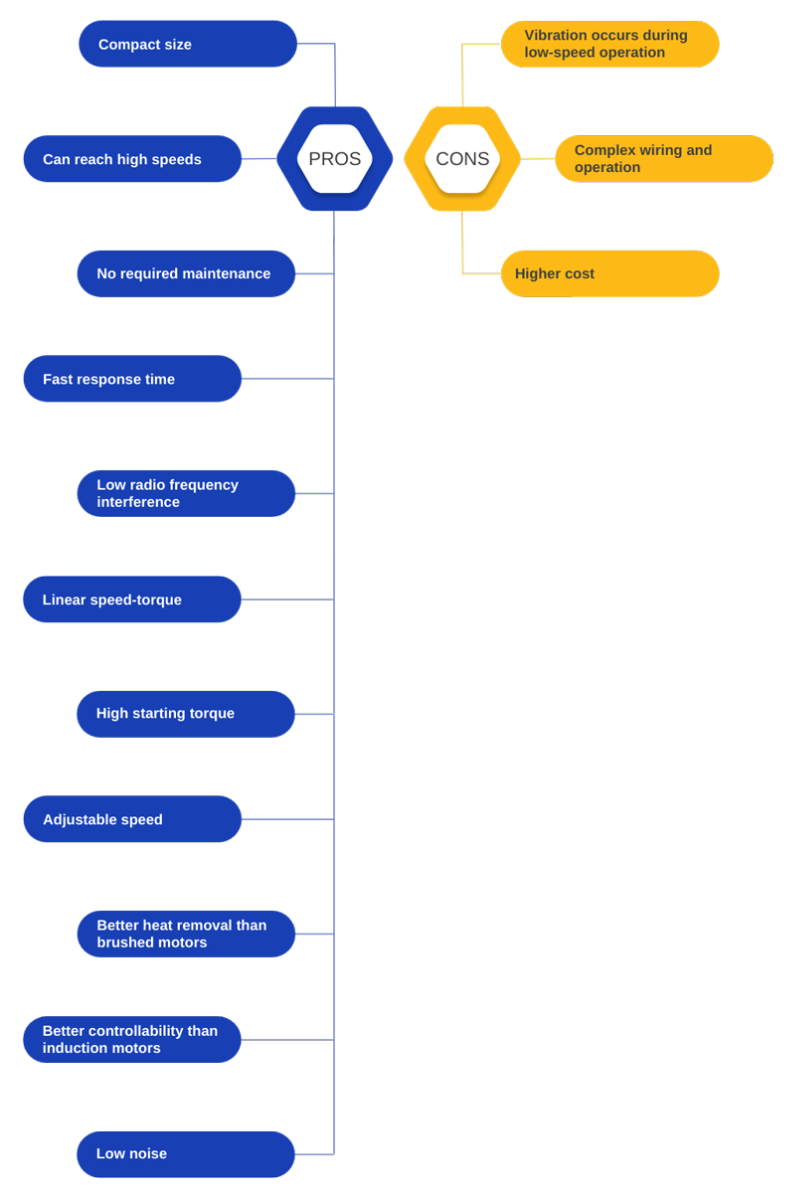
Pros and Cons of BLDC Motors
Brushless Motor vs. Brushed Motor
Why is a Brushless Motor Better than a Brushed Motor?
The absence of brushes in a brushless DC motor is perhaps its greatest advantage. The carbon brushes within a brush DC Motor wear out rapidly and need replacing, which can be costly in the long run. The brushless DC motor generates less noise and is less prone to sparking due to the lack of a commutator. The brushless DC motor is typically smaller and lighter than the brush DC motor, making it ideal for applications where weight and space are important factors. The brushless DC motor is cleaner, more powerful, and requires lower maintenance than does the brush DC motor. It has higher speed ranges, higher dynamic responses, and ultimately outlasts the brush DC motor in total operating hours.
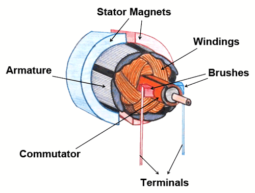
Diagram of a Brushed DC Motor
Image source: the Clemson University Vehicular Electronics Laboratory
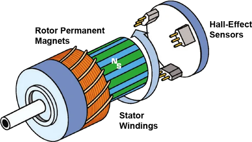
Exploded Diagram of a Brushless DC Motor
Image source: medicaldesignbriefs.com
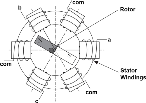
Schematic Diagram of a Three-Phase BLDC Motor with One Pair of Rotor Permanent Magnet Poles
Image source: researchgate.net
When could a Brushed Motor be Advantageous over a Brushless Motor?
There are numerous applications using a brush DC motor that could instead utilize the brushless DC motor. However, a few factors might prevent the changeover. The first factor is start-up cost. Although the brushless DC motor is lower-maintenance than the brush DC motor, initial cost is more expensive due to its advantageous construction. Second is complexity. BLDC motor controllers are more complicated to use than brush DC motor controllers. A brushless DC motor also requires additional system wiring in order to power the electronic commutation circuitry.
Lifetime of a Brushless DC Motor
The brushless DC motor is often considered superior to the brush DC motor for its substantially longer lifespan. If run within the given specifications, the brushless DC motor can last over 20,000 operating hours, dependent on bearing life. Running a brushless DC motor outside of its specifications shortens this lifespan.
Required Maintenance of a Brushless DC Motor
Due to the lack of brushes or a commutator, there is nothing that needs to be replaced within a brushless DC motor, making it extremely low maintenance. The only requirement is that the motor be run within proper specifications and a clean environment to ensure it does not overheat or result in system failure.
Brushless DC Motor Environmental Considerations
Precaution must be taken by the user with respect to the environment of the brushless DC motor system during operation, repair, and service. The environment in which a brushless DC motor is used must be conducive to good general practices of electrical equipment. Do not run a brushless DC motor system near flammable gases, dust, oil, vapor or moisture. The brushless DC motor must be protected by a cover if operated outdoors, ensuring the motor receives adequate air flow and cooling. Any presence of moisture may result in system failure and/or electric shock. Therefore, adequate care should be taken to avoid any interaction between the brushless DC motor and any kind of moisture or vapors. A brushless DC motor should be installed in an environment free from vibration, shock, condensation, dust and electrical noise. Anaheim Automation carries a full line of IP65 Rated Sealed Brushless DC Motors for operation in harsh and humid environments.

Avoid Flammable Gas, Dust, Oil, and Vapor
Note: Any failure to observe the aforementioned safety and environmental precautions violates the manufacturing standards and intended use of the brushless DC motor, and will also void the warranty.
Troubleshooting a Brushless DC Motor
Please note: Anaheim Automation offers technical assistance free of charge to help the customer in product selection, installation, and servicing. However, while accurate guidance, technical data, and illustrations are intended to properly assist the customer regarding the brushless DC motor line and other products, such advice and documents are subject to change and solely supplementary. The customer is ultimately responsible for the appropriate selection and operation of their brushless DC motor system.
Problem: The brushless DC motor is running incorrectly, or stops running.
Solution: A brushless DC motor having difficulty operating could indicate that the Hall effect sensors are damaged. To check, use a resistor to pull each Hall effect sensor output up to 5 volts, and check each output with an oscilloscope while spinning the shaft. Monitor the point between the sensor output and the resistor as pictured in Figure 2.
Repeat this process for each individual Hall effect sensor output. When spinning the shaft manually, a low and high signal should appear on the scope. Keep in mind the resistance value; this depends on the amount of current the Hall effect sensors can withstand.
If this test demonstrates that the Hall effect sensors are working correctly, the next step is to check the phases of the brushless DC motor. Hook up the brushless DC motor to a controller. With an oscilloscope, check each phase to see if a switching signal is present. If the phases do not pose a problem, this may indicate a bearing problem or internal shorts. If these techniques do not seem to explain why the brushless DC motor is working improperly, the purchase of a new brushless DC motor should be considered.

Figure 1: Hall Sensor Test Circuit Configuration

Figure 2: Hall Sensor Test Pull Up

Figure 3: Hall Sensor Test Oscilloscope Image
Formulas for BLDC Motors
What is the Kt Constant in a Brushless DC Motor?
Winding Power = Kt2 / R
Kv = 1000 rpm / Vrms
Kt = oz-in / Amp
Kt = Kb * 1.35
Ke = Vrms / 1000 rpm
Kb = V / 1000 rpm
Back EMF = V/KRPM
History of a Brushless DC Motor
British scientist Michael Faraday first experimented with the idea of the electromagnetic induction motor in the early 1800's. By 1828, the DC motor was introduced with three main components: the stator, rotor, and commutator. During that time, DC motors did not contain permanent magnets. Instead, they operated similarly to today’s brush DC motors in that they had current flowing through the windings of the motor. In 1837, Americans Thomas and Emily Davenport transformed Faraday's DC motor into one that could be used commercially. These DC motors became popular in printing presses and powered machine tools. However, with the high cost of battery power, the demand was too low to keep them successful. In 1886, Frank Julian Sprague introduced the first practical DC motor that was capable of constant speed under variable loads.
Overtime, the elimination of the commutator and brushes made room for the introduction of electronic commutation. Although the brushless DC motor was quite expensive when first introduced, the advancements in design and materials drastically lowered costs and made the brushless DC motor a popular selection for many different applications.
Brushless Motor FAQs
Q: Can voltages other than the specified voltage be applied?
A: Yes, you can apply different voltages, although you must keep in mind that there is a speed limit for the bearings. If you increase the voltage, the speed will increase. If you decrease the voltage then the speed will decrease. For example, if a brushless DC motor is rated to run at 3000 RPM, no load, with 36VDC, the motor will run 2000 RPM with 24VDC. The maximum speed, torque, and power are directly proportional to the voltage.
Q: How can I achieve a higher power output without purchasing a new motor?
A: This can be approached in two ways: increasing the applied voltage or increasing the current supplied to the motor. The voltage is related to the speed and the current is related to the torque.
Power =

Power = Watts (W)
τ = Torque (oz-in)
ω = Speed (RPM)
In the BLDC motor torque curve below, it can be seen that as the torque increases, current increases, and also as the voltage increases, speed increases.
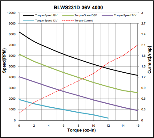
Brushless Motor Torque Curve
Q: Do Hall Effect Sensors need to be used to drive a brushless DC motor?
A: No, Hall effect sensors are only needed for feedback systems that require them. A brushless motor may be sensorless where the back EMF is used to run the motor.
Q: How many pulses per revolution for one Hall effect sensor in a 4 pole and 8 pole motor?
A: 4 Pole motor has 2 pulses per revolution: 4/2 = 2 Pulses
8 Pole motor has 4 pulses per revolution: 8/2 = 4 Pulses
Q: Are brushless motors waterproof?
A: Brushless motors may be water resistant, but are not inherently waterproof. Tiny water particles can seep into the bearings and wear them away. Anaheim Automation supplies splash-proof, IP65 Rated Sealed Brushless DC Motors for use in humid or damp environments.
Q: Are brushless motors more efficient than brushed motors?
A: Brushless motor efficiency is much higher than that of brushed motors. Brushless motors are 85-90% efficient while brushed motors are 75-80% efficient.
Q: Are brushless motors faster than brushed motors?
A: Yes, brushless motors are faster due to the lack of friction between their moving parts and higher efficiency, which allows them to convert more energy into mechanical power.
Q: Are brushless motors quieter than brushed motors?
A: Yes, brushless motors generate less noise than do brushed motors because they do not contain brushes. Since there are no brushes, there is less noise created by movement.
Q: What is stall torque?
A: Stall torque is the torque at which the shaft ceases to move.
Q: What is rated torque?
A: Rated torque is the torque at which the motor can operate continuously at a safe level.
Q: What is peak torque?
A: Peak torque is the torque at which the motor can operate for a brief period of time. Motors will be damaged if run at peak torque for long periods of time.
Q: Can I run a brushless DC motor off of a battery?
A: Yes, along with a Brushless DC Controller.
Q: Can I run a brushless DC motor off of 110 VAC?
A: Yes, along with a brushless DC controller.
Q: Will a brushless DC motor slow down when the load is increased?
A: In closed-loop control, the brushless DC motor will not slow down as long as the torque of the motor is strong enough. However, it will always slow down with open-loop control.
Q: Is it possible to burn a brushless DC motor by applying too much load?
A: Yes, it is possible to burn the motor by apply too great a load, but it is protected if the controller has a current limit provision.
Q: What is the recommended cable distance between Anaheim Automation BLDC motors and drivers?
A: We recommend that the wiring between BLDC motors and controllers not exceed 25 feet in length. Although not required, we suggest using Anaheim Automation’s shielded motor cable. This cable is ideally suited to handle all driver/motor combinations that we offer. We can also add connectors to the cables. Please contact an applications engineer for more details.
Q: Does Anaheim Automation sell encoders for BLDC motors?
A: Yes. We supply encoders of any order size to customers who require a complete motor/encoder assembly ready to mount. We can assemble the encoder to the motor for a nominal charge. Ask one of our customer service representatives for more details.
Q: What is the life expectancy of Anaheim Automation’s BLDC Motors?
A: Anaheim Automation’s BLDC motors have a 20,000-hour life expectancy under normal operating conditions. Anaheim Automation's warranty is 12 months after the invoice date. See the "environmental considerations" sections of the BLDC motor guide for more details.
Q: Can a disassembled BLDC motor be cause for damage?
A: Yes, disassembling the motor can lead to further damage and malfunction. Additionally, disassembling an Anaheim Automation motor will void your warranty. If you have a motor failure or are concerned about the performance, contact Anaheim Automation. Please note that the warranty period is 12 months from the date of invoice.
Q: What should I do if my motor stalls at high speed when the temperature exceeds 65° C?
A: Try to keep the BLDC motor below 60° C or move up one stack length in your motor.
Q: Does Anaheim Automation offer custom BLDC motors?
A: Yes, we offer BLDC motors with added encoders, cables and connectors. We also offer custom motor shafts and windings, private-labeling, footprint-matching, and more. Some "special" motors are non-stock items that may require an NRE or SET-UP charge. The NRE and SET-UP charges are occasionally waived for orders of large volumes. Many Anaheim Automation BLDC motors come standard with shaft-flat and/or encoder-ready provisions, in which case there would be no additional fees for these features. Check the specification sheet and individual dimension drawings for details.
Custom AA Motor with Value-Added Gearbox, Pulley, Encoder, and Connector
Q: Can I get a BLDC motor and Speed Controller assembled together?
A: Yes, Anaheim Automation offers Integrated BLDC Motors/Controllers. Check our BLYMD, BLWR23MD, BLWR23MDA, BLWS23MD and BLWSMDA series for more details.
Q: Can I add an encoder to BLDC motors?
A: Yes. We supply encoders of any order size to customers who require a complete motor/encoder assembly ready to mount. Encoders provide valuable system feedback, enabling more precise system control. We can assemble the encoder to the motor for a nominal charge. Contact one of our customer service representatives for more details.
Q: Is any maintenance required for a BLDC motor?
A: Due to the lack of brushes or a commutator, there is nothing that needs to be replaced within a BLDC motor, making it extremely low maintenance. The only requirement is that the motor be used in accordance with its published specifications and in a clean environment to ensure it does not overheat or result in system failure.
Q: Are there any environmental considerations I should be aware of to operate a BLDC motor and controller?
A: Precaution must be taken by the user with respect to the environment of the BLDC motor during operation, repair, and service. The environment in which a BLDC Motor is used must be conducive to good general practices of electrical equipment. Do not run a BLDC motor near flammable gases, dust, oil, vapor or moisture. The BLDC motor must be protected by a cover if operated outdoors, ensuring the motor receives adequate air flow and cooling. Any presence of moisture may result in system failure and/or electric shock. Therefore, adequate care should be taken to avoid any interaction between the motor and any kind of moisture or vapors. A BLDC motor should be installed in an environment free from vibration, shock, condensation, dust and electrical noise. Anaheim Automation carries a full line of IP65 Rated BLDC motors for operation in harsh, humid environments. Please refer to our Installation and Environment guide for more information.