We use cookies to make your experience better. To comply with the new e-Privacy directive, we need to ask for your consent to set the cookies. Learn more.
EMI Noise Checklist
EMI Noise Checklist
Understanding EMI – Electromagnetic Interference in Motion Control Systems
Electromagnetic Interference (EMI) is the unwanted radiation or induction of electromagnetic signals in a system or machine. This electromagnetic noise may degrade the performance of equipment (device, system, or sub-system), or cause equipment to malfunction. In addition to degraded system performance, EMI may also lead to data corruption, or – when it is very strong – complete system failure. Electromagnetic noise can either be radiated from magnetic sources, or conducted from electrical sources. Stepper motors, BLDC motors, servo motors, and other electric motors can generate common-mode currents and are a potential source of EMI. In the case of most motors, both radiated and conducted emissions are present.
Possible Effects of EMI in a motion control system:
• Intermittent disturbances in the drive and controllers
• Computers and HMIs may falter and lose data, causing to reset/start-up
• Burn-out of sensitive components
• Disturbances in the settings and status registers of control equipment
• Lower productivity
Jump to section: EMI Checklist - Quick Tips for Motion Control Systems
Sources of Electrical Noise
Electrical noise is always present in an electrical system. Communication receivers, microprocessors, industrial drives and controls, medical devices, and household appliances are all susceptible to electromagnetic disturbance. Electrical noise may come from natural (solar flares, lightning) or man-made sources.


Sources of EMI may be natural or man-made
Typical Causes of EMI
Industrial:
Arc welding, motors, computers, fast-switching digital devices, Integrated Circuits, power cords.
Military:
Aircraft navigation and equipment
Household:
Refrigerators, washers, dryers, dishwashers, electric shavers, personal computers, air-conditioning and heating systems.
Enclosure Lights
Fluorescent lamps are also sources of EMI. If you must use fluorescent lamps inside an enclosure, the following precautions may help guard against EMI problems from this source:
-
- Install a shielding grid over the lamp
- Use shielded cable between the lamp and its switch
- Use a metal-encased switch
- Install a filter between the switch and the power line, or shield the power-line cable
Arcing:


Arcing (sometimes referred to as arc discharge or voltaic arc) is an electrical characteristic where current flows through the air, or other normally non-conductive materials. You may have seen arcing between two wires, or on the power rails of trains or trams. This is similar to an electrical spark, however, an electrical arc is continuous, and a spark is not.
While arcing can be useful – it is used in both welding and strip lighting – in some cases, it can be an unwanted source of EMI. For example: with DC motors, arcing is common because of the periodic interruption of the current in the rotor windings. This causes very high-frequency spectra content, which can appear as wideband noise superimposed onto other signals in your system. DC motors also provide paths for common-mode currents through their frames.
Driver Circuit:
Radiated and conducted emissions can also come from the driver circuit. Ideally, a typical H-bridge circuit should provide a constant current to the motor, but this current has fast rise time spikes due to the fast and frequent switching of the current in the driver circuit.
Another significant problem is when the motor is located far from the driver, as this creates a fairly large loop area between motor leads and device frame. The radiation potential is a direct function of the loop area – the larger the loop, the larger the emissions.
Power Line Interference:


Image source: Wikipedia
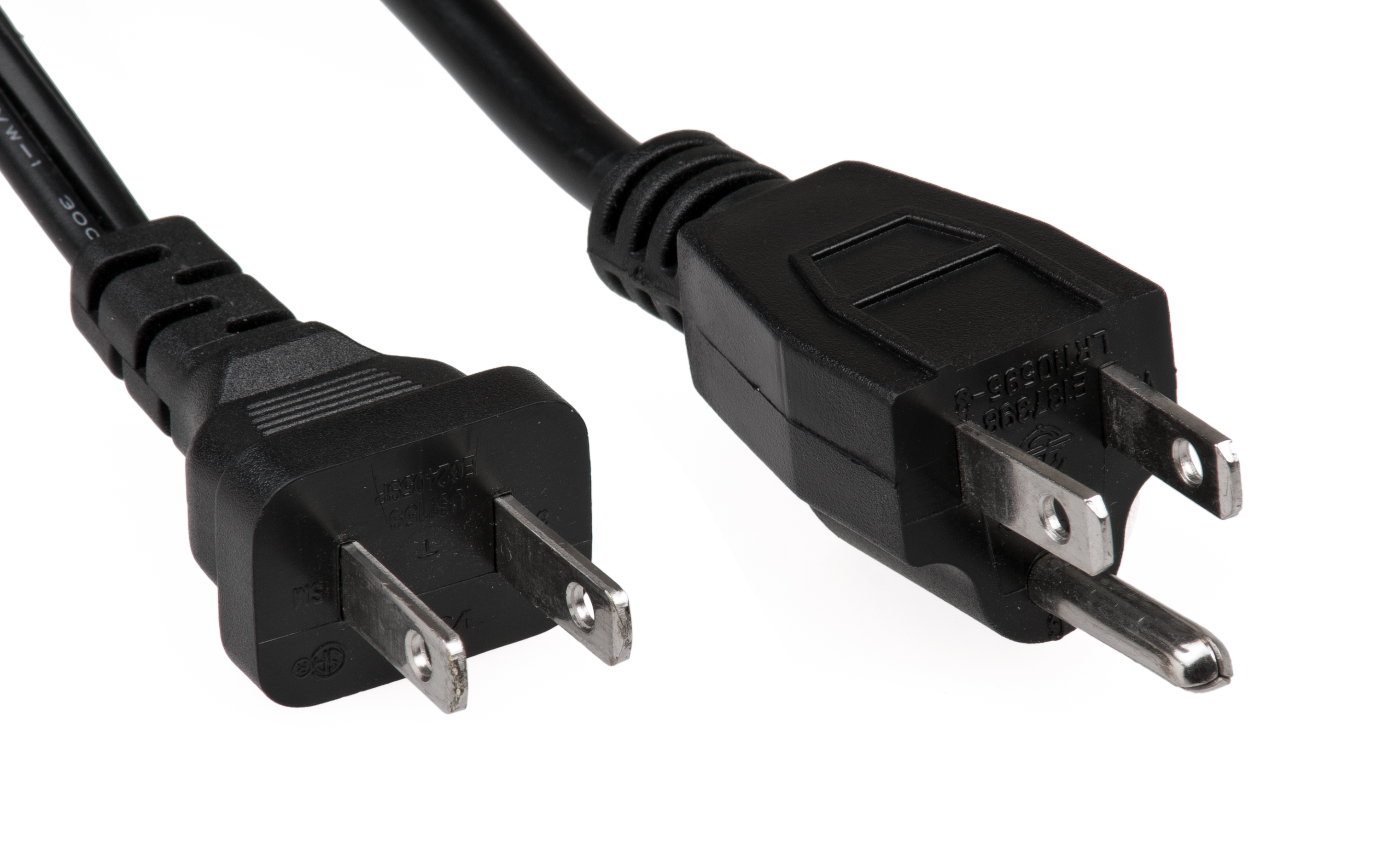
Power lines are one of the most troublesome sources of electrical noise. The power lines to which the motion control components are connected may also supply power to equipment such as arc welders, high current (induction) furnaces, or large horsepower electric motors. Starting or stopping these large consumers of power, or changing the load conditions on them, may cause transient voltages, which may take the form of voltage surges or dips, accompanied by high frequency noise superimposed on the incoming voltage waveform. This electrical noise may cause a digital electronic control system to count incorrectly, lose stored data, store incorrect data, or lose axis synchronization.
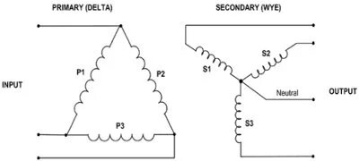
Power lines in an ungrounded Delta power system are inherently noisy. This system floats with respect to ground, and may cause excessive voltage to be applied to equipment connected to it. For these reasons, a grounded Wye power system is preferred for supplying power to a computer-controlled machine tool or other motion system.
If the only available power source is an ungrounded Delta type, install a Delta-to-Wye isolation transformer ahead of the control. Ground the neutral of the Wye to improve noise rejection and to better regulate the input voltage to the controls.


Image source: physicsforums.com
To minimize the effects of power line noise on computer-controlled machine tools, or other motion control system components, power wiring should be physically and electrically separated from the logic signal wiring. Install a motor alternator set ahead of the control to isolate it from the incoming power line.
Shielded cables should also be used for logic signal wiring where appropriate, and an effective common point ground system should be provided. Even if these precautions are taken, power line noise may still be coupled into the logic in extreme cases, and cause the control to malfunction.
EMC – Electromagnetic Compatibility
Electromagnetic Compatibility is the practice of monitoring and reducing unwanted EMI. Electromagnetic compatibility describes a near-perfect state in which a receptor (device, system, or sub-system) functions well in a common electromagnetic environment, without introducing intolerable electromagnetic disturbance to any other devices, equipment or systems that share the environment.
IMPORTANT NOTE:EMC performance concerns the complete motor and drive system, including all motion system components and machinery. Therefore, it is the responsibility of the end-user, integrator, or system designer –not those who supply motion control products – to monitor and reduce undesirable EMI. Regulations on EMC vary, depending on the purpose of the system and the country or region in which it is used or sold.
A motor and drive are considered to be electromagnetically compatible if:
-
- The motor and drive do not cause interference with each other
- The motor and drive are not susceptible to EMI emissions from other components in the system or machinery
- The motor and drive do not cause interference within themselves
EMI Reduction Techniques to Improve Systems' EMC Performance
It is typically a simple matter to minimize electrical noise. Proper cable selection and shielding are essential – always make certain to use a shielded cable with the correct number of wires which has been securely grounded at either the motor or drive. Be sure to keep the cables as short as possible, preventing them from coiling/looping around themselves. Keep as much distance between any communication cables and high-voltage cables as possible. Following these guidelines will help to minimize electrical noise in your system.
Prevent EMI Problems
-
- Suppress possible emissions at the source point.
- Reduce components' susceptibility to EMI emissions by ensuring proper mounting and installation.
-
Make the coupling path as inefficient as possible.
EMI Control Techniques at Source Point:
-
- Proper Grounding – Single point, multi-point, or hybrid grounding depending on the frequency of the operation
- Shielding – metal barrier used to suppress coupling of radiated electromagnetic energy into the equipment.
- Filtering – filtering techniques are used to suppress conducted interference on Power, Signal, and Control lines.
- Printed Circuit Board (PCB) – Proper design and layout of printed circuit boards from the early design stage is essential to eliminate EMI issues in the future.
- Noise Coupling – conductive coupling through cables, coupling through common impedance, and ground loop coupling techniques are good preventative measures against EMI issues.
Standard Components
To control EMI at the source point, the easiest solution is a ceramic capacitor placed between the motor terminals, as close as possible to the motor. This is known as a decoupling capacitor, and reduces EMI by removing some of the high frequency noise signals. The common value used for these decoupling capacitors is between 100pF and 100nF, depending on the size of the motor and other system factors.
Shielded I/O Cables - General Practices
Certain I/O connections require shielded cables to help reduce the effects of electrical noise coupling. Follow the specific instructions in the manufacturer’s publication provided for each specific product.
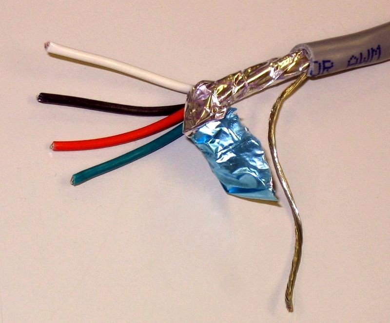
Ground each shield at one end only. A shield grounded at both ends forms a ground loop, which can cause a processor to fault. Never connect a shield to the common side of a logic circuit (this would introduce noise into the logic circuit).
Connect each shield directly to a chassis ground. For some communication network cables, the shield connections are unique to the particular cabling system. In such cases, a DC short to ground is not needed because a low-impedance AC path to ground, and a high-impedance DC path to ground, are provided internally at each node.


Image source: Wikipedia
IMPORTANT NOTE: EMC is an important field in electronics with strict regulations, and motors and their circuits are significant sources of EMI. It is essential that engineers/system designers/operators take the appropriate actions to reduce EMI and improve EMC as much as possible.
EMI Checklist – Quick Tips for Motion Control Systems
The following checklist can be used as a quick reference guide to help system designers and operators avoid electromagnetic interference (EMI) problems in motion control applications:
-
- To avoid the possibility of electrical shock, perform all mounting and wiring of a motor and driver system prior to applying power.
Once power is applied, connection terminals may have voltage present. - Follow the wiring diagram (and any other instructions from the manufacturer) for each component in the system.
-
Use the manufacturer's cables.
Machine builders who use product-specific power and feedback cables experience fewer problems than those who make their own cables. Matched cable and product sets will not only help to eliminate EMI, they also provide for quick and easy hook-ups.
Anaheim Automation provides shielded cables, designed to minimize EMI, for use in motion systems. These cables are recommended over customer-built cables to optimize system performance, and to provide additional safety for both the system and the user.
- Keep cable lengths as short as possible.
Lengths shorter than 25 feet are recommended. - Use shielded cable for power wiring and provide a grounded 360 degree clamp termination to the enclosure wall.
Allow room on the panel for wire bends. - Ensure good shield connections.
For particularly noisy scenarios, such as with cables entering a cabinet, never connect a simple “pigtail.” Connect shields on all 360 degrees of the cable. - Splice cables properly.
Connectors with metal backshells should be used whenever cables must to be divided. Both shells need to connect along the full 360 degrees of the shield. NOTE: No portion of the cabling should be unshielded. By no means should cable be divided across a terminal strip. -
Use common-mode chokes on motor leads.
Cables exceeding 75 feet in length may require motor common-mode chokes. Check with an Anaheim Automation Applications Engineer for more details. -
Route high-voltage power cables separately from low-voltage power cables
in order to maintain effective insulation resistance. -
Separate signal cables from motor/power cables.
Always bundle and route control/feedback cables separately from motor/power cables, and maintain the separation throughout the wire run. Power cables may cross-conduct and disrupt signals in control cables if not properly separated. -
Use differential inputs for analog signals
Using differential outputs can greatly reduce noise susceptibility in analog signals. Connect the output signal to the positive differential input and the ground of the device generating the output to the negative differential input. Use twisted-pair shielded cable lines, connecting shields on both ends. -
Ensure good connections between the cabinet components
Use multiple conductive braids to connect the cabinet body to both the back panel and cabinet door.
CAUTION: Never rely on mounting bolts or hinges for ground connections.Set up an electrical connection across the back surface of the drive panel or cabinet. It is preferred that the user do this with electrically-conductive panels, such as galvanized steel or aluminum.
-
Ensure good ground connection.
Connect the cabinet to the appropriate earth ground. The ground leads should be the same gauge or a gauge smaller than the leads to the main power source. -
Use a grounded Wye power system whenever possible for supplying power to a computer-controlled machine tool or motion system.
If an ungrounded Delta type is the only available power source, install a Delta-to-Wye isolation transformer ahead of the control.
- To avoid the possibility of electrical shock, perform all mounting and wiring of a motor and driver system prior to applying power.
Qualified Professionals Only
Electrical wiring is complicated and potentially life-threatening if installed incorrectly. Do not attempt to install a motor and drive, or any other Anaheim Automation product, or other electrical equipment, unless you are certain you have received the proper training and education for the task. This is one area of business you can't afford to be frugal about. If you are not sure how to do the motor and drive installation, always hire a qualified electrician/panel builder/integrator. A motor and drive system should never be operated around water, dust, or flammable materials. Adherence to proper safety guidelines can save lives and valuable property by preventing electric shock and fires.
