We use cookies to make your experience better. To comply with the new e-Privacy directive, we need to ask for your consent to set the cookies. Learn more.
Stepper Actuator Guide
Table of Contents
What is a Stepper Actuator?
A stepper actuator, or stepper linear actuator, is an electromechanical device which produces force, as well as motion, along a straight path. A stepper actuator uses the core principles of a stepper motor, with some slight modifications.
With the stepper actuator, the shaft of a normal stepper motor is replaced with a precision lead screw, and the rotor is tapped to convert it to a precision nut that is adjusted to the lead screw.
As the rotor rotates, the lead screw rotates up and down the precision nut, creating linear motion without the need for outside mechanical components. In this way, stepper actuators can simplify many rotary-to-linear applications, while offering high resolution and accuracy.
Stepper actuators can be operated over a wide range of speeds, and can be used to drive almost any load commonly encountered.
34A Series Stepper Actuator with Non-Captive Screw
Physical Properties of a Stepper Actuator
Stepper linear actuators are made up of the same core properties as a stepper motor, with some modifications. The main components of a standard stepper motor are the shaft, magnetic rotor and stator laminations, bearings, copper motor windings, and lead wires, washers, and front and end covers. In a stepper linear actuator, the shaft of a normal stepper motor is replaced with a precision lead screw, and there is a tapped precision nut within the center of the rotor, which interacts with the lead screw to create linear motion. The motor windings, long coil of copper wire, are wound around the stator to channel electromagnetic energy into the rotor to rotate the motor. The stator and rotor laminations are comprised of silicon steel, which allows for a higher electrical resistivity and lower core loss. There are a variety of magnets used: ferrite plastic, ferrite sintered, and Nd-Fe-B (neodymium magnet).
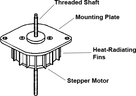
Components of a PM Stepper Actuator with Threaded Shaft and Mounting Plate
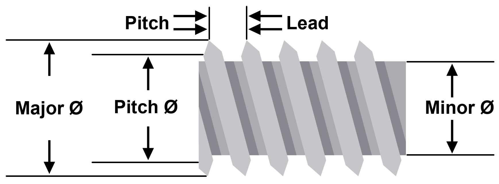
Illustration of the threaded shaft with the pitch and lead screw
How do Stepper Actuators Work?
A stepper actuator is driven by a stepper motor driver and/or controller, which provides the instructions to command the stepper actuator to start or stop. The driver and/or controller sends electrical signal pulses to sequentially activate the phases of the actuator, causing the rotor (precision nut) to rotate and the lead screw to extend or retract. By sending electrical pulses as instructions, the controller designates how far and how fast the stepper actuator should extend or retract. A controller can be either pre-programmed or controlled in real time by inputs predefined on the stepper drive or controller.
How are Stepper Actuators Controlled?
Stepper actuator motors are typically controlled by a driver and controller, which dictate the speed, direction and distance traveled.
The controller creates clock pulses and direction signals that are accepted by the driver, which translates them into appropriate phase currents before supplying them to the actuator motor. The driver performs the conversion of logic pulses by sequencing power to the actuator windings; generally, one supplied pulse will yield one rotational step of the actuator. Due to the driver, the stepper actuator increments a precise amount with each control pulse, converting digital information into exact incremental rotation without the need for feedback devices such as tachometers or encoders. A computer or PLC (Programmable Logic Controller) can be used as the controller and integrated with an HMI to make the application user-friendly.
Block Diagram of a Stepper Actuator System
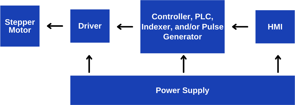
Stepper Linear Actuator System
Type of Stepper Actuators
How a Captive Linear Actuator Runs
Captive Stepper Actuators
Captive Stepper Actuators, also known as "rotating screw stepper actuators," have a built-in anti-rotational mechanism. A splined output shaft allows the actuator to extend and retract as a whole unit. These types of actuators are designed for applications which call for shorter stroke lengths.
How a Non-Captive Linear Actuator Runs
Non-Captive Stepper Actuators
Non-Captive Stepper Actuators, also known as "rotating nut stepper actuators," have a lead screw extending through the motor without any stroke limitations, but must be securely assembled on a piece of machinery or equipment which will not rotate. This allows the lead screw to extend and retract without rotating while the motor remains stationary. These types of actuators are used for applications requiring longer stroke lengths.
How an External Linear Stepper Actuator Runs
External Linear Stepper Actuators
External Linear Stepper Actuators, also known as "traveling nut stepper actuators," use a lead screw and nut combination that extends out from the motor. As the lead screw rotates, linear motion is created as the nut travels back and forth along the screw. External linear actuators are ideal for applications which require short stroke lengths.

Non-Captive, Captive, and External Linear Stepper Actuators
As discussed in an earlier section, stepper actuators are comprised of the same core components as basic stepper motors, with some modifications. Stepper actuators may use different types of stepper motors in their construction, i.e. Variable Reluctance (VR), Permanent Magnet (PM), or Hybrid stepper motors. To learn more about these different types of stepper motors, and how they operate, please refer to our Stepper Motor Guide.
How to Select a Stepper Actuator
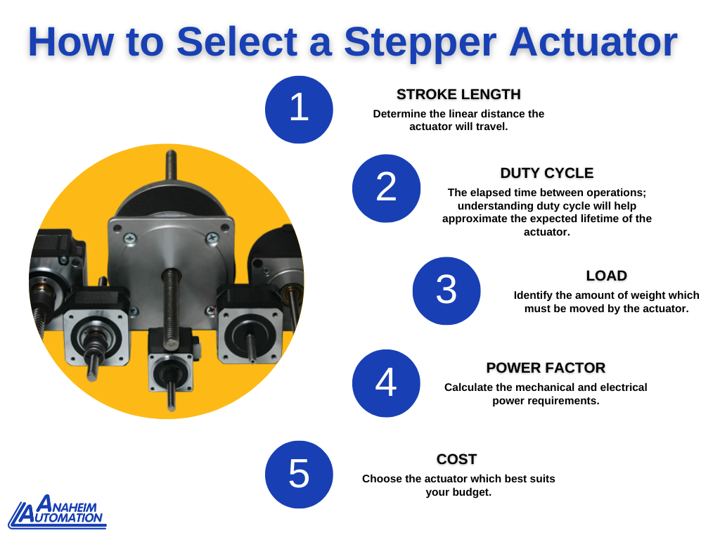
Stroke Length
In determining the right stepper actuator for a specific application, it is necessary to understand stroke length. Stroke length describes the linear distance the actuator will travel. The stroke length allows the device to handle short or long operational distances. Most, but not all, stepper actuators have a stroke length that allows the actuator to move a specific amount. For example, a small actuator could move a curtain for a home window, while a large actuator could move a curtain for a movie screen. As a result, a longer stroke length will increase the price of a linear actuator. Extra length is rarely required, so users should select stepper actuators that exactly fit the application.
Duty Cycle
Understanding the duty cycle, the elapsed time between operations, will provide a reasonable approximation of the expected lifetime of a stepper actuator. The duty cycle can be based on units of hours per day, minutes per hour, or strokes per minute. By managing the duty cycle one can increase the lifetime and the necessary maintenance required for the stepper actuator.
Load
One of the criteria for selecting a stepper actuator is to identify the amount of force required for the application. Defining the load required for the application will help identify the proper size and capabilities needed of the stepper actuator. Orientation also plays a key role in selecting the proper stepper actuator. With a stepper actuator in a horizontal position, calculating the overall load capabilities requires compensating for frictional force. When an actuator is mounted in a vertical position, it is especially important to consider weight due to gravitational force in load calculations.
Power Factor
Determine the mechanical power requirements of the application (linear force, speed) in order to determine the electrical specifications required of the actuator.
Mechanical Power:
Mechanical power is equal to speed x force: multiply the linear force required to move the load by the speed at which the load will be moved.
Determining the Linear Force the actuator is capable of pushing/pulling:
Convert the screw's lead to a radius:
Lead(in inches)/2π = Pr (Pulley radius)
Divide Torque (t) by Pulley radius (Pr) to get Linear force (Lf)
t/Pr = Lf (linear force)
If Torque is in oz-in, divide by 16 to convert Lf units to Pounds (lb)
Lf/16 = LbF (Linear Force in Pounds)
Multiply LbF by the Screw's Efficiency (%) to get the Net Linear Force (in Pounds) that the actuator is capable of producing
LbF * Efficiency = Net Linear Force
Example:
- Lead: 0.200 in.
- Torque (t): 100 oz-in
- Screw Efficiency: 80%
Pr = (0.200 in)/2π = 0.0318 in
Lf (linear force) = (100oz-in)/0.0318in = 3144 oz.
LbF (linear force) in Pounds = (3144 oz)/16 = 196 lb
196lb x 80% = 157 lb Net Linear Force
Electrical Power:
Electrical power specifications are obtained through performance graphs illustrating force vs. speed. These force curves are a good representation of the performance of a stepper linear actuator. Note: performance graphs are specific to each stepper actuator model.
Cost
Stepper actuator pricing varies, and is typically affected by size, function, accuracy, stroke length, and linear force. Certain types of actuators are more expensive than others, and pricing will vary from manufacturer to manufacturer, even for the same type.
Anaheim Automation offers both Hybrid and Permanent Magnet (PM) Stepper Actuator types. Hybrid types, owing to their superior capabilities, are generally more expensive than Permanent Magnet types. View our product pages to compare pricing for standard models (1-100pc pricing is published on each Series page):
-
Hybrid Stepper Linear Actuators
- External Linear and Non-Captive models offered
- Permanent Magnet (PM) Non-Captive Linear Actuators
- Permanent Magnet (PM) Captive Linear Actuators
Customization, Value-Added Services, and Accessories
Customize your Anaheim Automation Stepper Linear Actuator! The list of modifications includes, but is not limited to:
- Custom screw length or pitch
- Custom nuts
- Custom mounting dimensions
- Custom speed, torque, and voltage
- Added oil seal for IP65 rating
- Value-Added components: integrated encoders, connectors, cables, and brakes
Along with stepper linear actuators, Anaheim Automation carries a comprehensive line of stepper drivers and controllers, power supplies, gearmotors, compatible gearboxes, and integrated stepper motor/driver packages. Additionally, Anaheim Automation offers optical, magnetic, and capacitive encoders for feedback control of position and speed, brakes, HMI and PLC, cables and connectors, linear guides, ball screws, and linear actuator tables.
For other applications requiring a motor, please consider Anaheim Automation's extensive line of stepper motors, brushless DC, brush DC, Servo, or AC motors along with their compatible drivers/controllers.
Stepper Actuator Modes
There are three excitation modes that are commonly used with stepper actuator motors: full-step, half-step and microstep. The following will explain the basics of the different modes.
Stepper Actuator – Full-Step
In full-step operation, stepper actuator motors step through their normal step angle. For example, a 200 step/revolution motor will take 1.8 degree steps in full-step operation mode. That is – 360 degrees per full revolution, divided by 200 steps/revolution, means the motor will "step" at a 1.8 degree step angle while in full-step operation mode. (360 / 200 = 1.8)
There are two kinds of full-step modes. In single-phase full-step excitation, only one phase is energized at-a-time. This mode should only be used where torque and speed performance are not important, i.e. where the motor is operated at a fixed speed and load conditions are well-defined. Problems with resonance can prohibit operation at some speeds. Single-phase full-step mode requires the least amount of power from the drive power supply of any of the excitation modes.
Stepper actuator full-step mode, single-phase
Dual-phase full-step excitation mode means two phases of the actuator motor are energized at the same time. This mode provides good torque and speed performance with a minimum of resonance problems. Dual excitation, provides about 30 to 40 percent more torque than single excitation, but does require twice the power from the drive power supply.
Stepper actuator full-step mode, dual-phase
Stepper Actuator – Half-Step
In half-step mode, alternating single-phase and dual-phase operation results in steps one half the normal step size. Half-step mode provides twice the resolution of full-step excitation (twice as many steps per revolution). For example, a motor with a 1.8 degree step angle, which takes 200 steps per revolution in full-step mode, will take 400 steps per revolution in half-step mode, giving it a 0.9 degree step angle (half the size of a full step). Half-step mode is commonly used because it offers almost complete freedom from resonance problems while remaining cost-effective.
Stepper actuator half-step mode
Stepper Actuator – Microstepping
In microstepping mode, a stepper actuator natural step angle can be divided into much smaller angles. For example, a standard 1.8 degree motor takes 200 steps-per-revolution. If the motor is microstepped with a 'divide-by-10' directive, then each microstep would move the motor 0.18 degrees and there would be 2,000 steps-per-revolution.
Typically, micro-step modes range from divide-by-2 to divide-by-256 (51,200 steps per revolution for a 1.8 degree motor). The micro-steps are produced by proportioning the current in the two windings according to sine and cosine functions. This mode is only used where smoother motion or higher resolution is required. Some microstep drivers have a fixed divisor (least costly) while other have a selectable divisor (most costly). Generally, the greater the divisor, the more costly the microstep driver will be.
The basics of microstepping
Advantages of Stepper Linear Actuators
- Minimize mechanical components
- Cost-effective design
- High resolution and accuracy
- High force output
- Long stroke lengths
- Many options in construction and functionality available
Disadvantages of Stepper Actuators
- Parts prone to wear (especially bearings)
Comparative Advantages and Disadvantages of Different Actuator Types
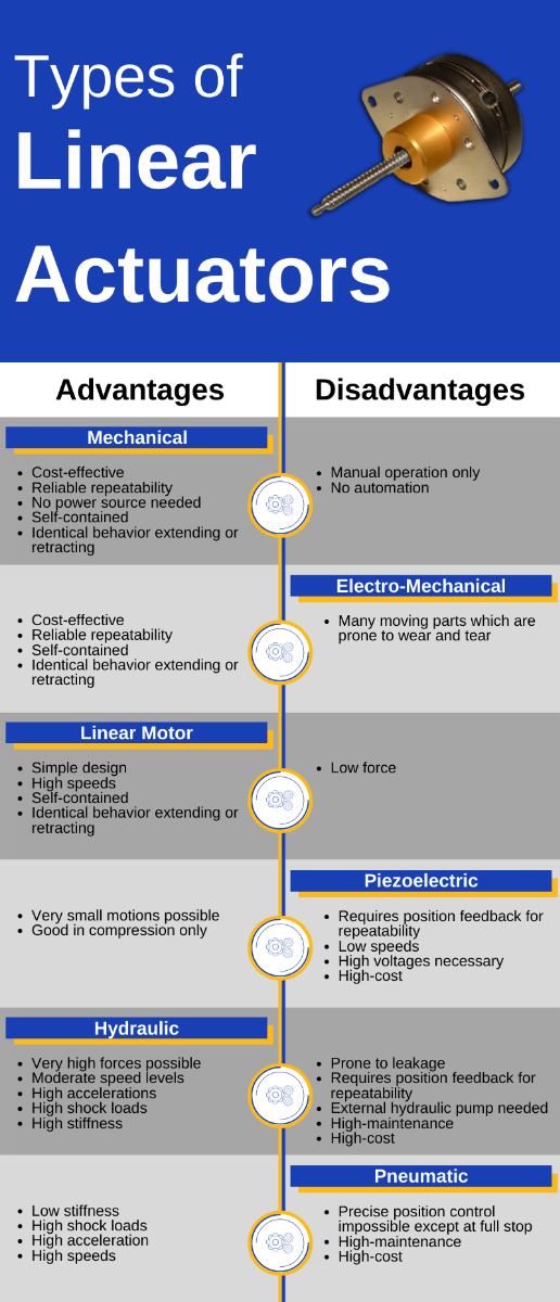
Common Applications for Stepper Actuators
With the increased demand for ever smaller, lower-cost machines, stepper actuators are designed to reduce the size and costs of motion control systems. While steppers are often overshadowed by servo systems in motion control, there are many applications in which steppers are actually the more apt technology to meet system requirements.
Where are Stepper Actuators Used?
Stepper actuators are common in both commercial and domestic applications, and are often used in such industries as:
- printing and labeling
- packaging
- electronic manufacturing
- medical industries
- laboratory instrumentation
- CNC machinery
- robotics
- X-Y tables
- valve control
- and many other applications requiring precise linear motion control
For example, in the Life Sciences industry, stepper actuators are often used in laboratory automation equipment in order to move specimen tables. Stepper actuators are great for this function because they offer precision and repeatability.
Another common use for stepper actuators is in 3D printing applications, where they are often found in the XYZ axis, controlling the movement of the print head.
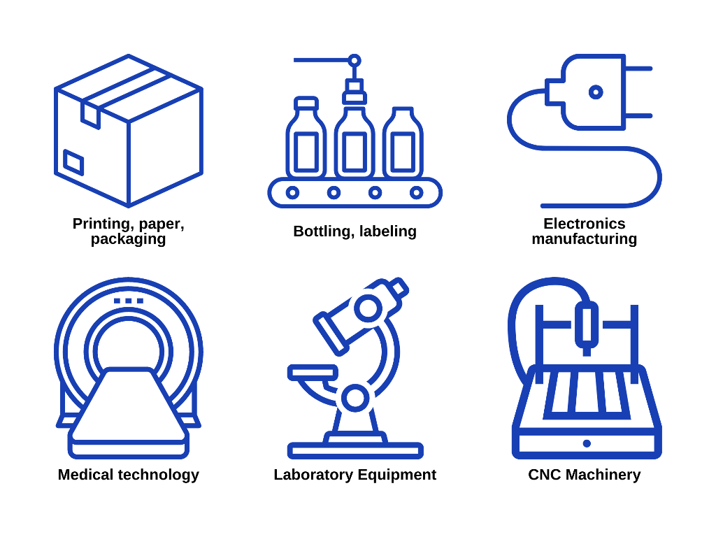
Stepper Actuator Applications
Environmental Considerations for Stepper Actuators
The following environmental and safety considerations must be observed during all phases of operation, service, and repair of a stepper linear actuator system. Failure to comply with these precautions violates safety standards of design, manufacture, and intended use of the product. Anaheim Automation, Inc. assumes no liability for the customer's failure to comply with these requirements.
Even well built products, operated or installed improperly, can be hazardous. Safety precautions must be observed by the user with respect to the load and operating environment. The customer is responsible for proper selection, installation and operation of the products purchased from Anaheim Automation, Inc.
Human safety and equipment safety must be the top priorities when performing the installation procedures for a stepper actuator system. When it comes to electronics in your factory or workplace, you want to make sure both your facility and the employees in it are safe. Please review the Safety section of our Installation and Environment guide for a basic electrical safety best-practices checklist.
- Use caution when handling, testing, and adjusting during installation, set-up, and operation
- Service should only be performed when power is completely shut off. To avoid the possibility of electrical shock, perform all mounting and wiring of the actuator and drive system prior to applying power. Once power is applied, connection terminals may have voltage present, even when the system is not in use.
- Any exposed circuitry should be properly guarded or enclosed to prevent unauthorized human contact, or exposure to moisture, dust, debris, and other environmental hazards
- All products should be securely mounted and adequately grounded
- Provide adequate air flow and heat dissipation
- Avoid operating in vibration and shock environments
- Do not operate in the presence of flammable gases, vapors, liquids, or dust

Avoid Flammable Gas, Dust, Oil, and Vapor
See our Installation and Environmental Considerations for Motion Control Systems article for more information.
Lifetime of a Stepper Actuator
The lifetime of a stepper actuator is dependent on several factors such as duty cycle, load, eccentric load, and temperature. Duty cycle represents the elapsed time between operations of the stepper actuator in hours per day, minutes per hour, or strokes per minute. Of course, heavier use will likely shorten the lifespan of a stepper actuator, while lighter use will have the opposite effect. An eccentric load is a load in which the center of gravity does not go through the screw axis. These types of loads cause binding and shorten the lifetime of an actuator.
Bearings are typically the limiting factor for stepper actuator lifespan, as they will fail before any of the other components, which could last almost indefinitely. Bearings have about 20,000 hours total lifespan. This estimate assumes normal use of about eight hours per day, five days per week. Thus, the lifetime for a stepper actuator is about 10 years, assuming proper operating conditions.
Staying within the limitations of the load capacity the stepper actuator will help maintain its durability and lifetime. Exposing the stepper actuator to extreme temperatures can greatly reduce the overall performance and life of the motor. In sum, managing the duty cycle, load, and temperature, will maximize the lifetime of a stepper linear actuator. Always use a stepper actuator within the manufacturer's specifications.
Required Maintenance for a Stepper Actuator
The stepper actuator components which are most prone to wear are the lead-screw and the precision nut. After time, both components will begin to show effects of grinding and friction from coming into contact with one another. Limiting exposure to dust, debris, and harsh environmental conditions can reduce the burden of maintenance required on the actuator. Also, decreasing the duty cycle (e.g. hours used per day) can greatly reduce the required maintenance of the actuator and increase its lifetime.
Frequently Asked Questions
Does the lead screw rotate in a Non-Captive Linear Actuator?
No, non-captive linear actuators must be secured to a non-rotating unit. Once the unit is secure, the lead screw will actuate back and forth without rotating. Non-captive linear actuators are designed for longer stroke lengths.
My stepper motor/actuator appears to be getting extremely hot when in the holding position. Is this a normal occurrence?
When an actuator's holding current is equal to its specific rated current, the motor/actuator will have an 80°C rise in temperature. This is normal operation temperature of the actuator. Actuators generally use Class B insulation, so internal maximum temperature is 130°C, making allowable ambient temperature 50°C. To minimize the heat rise in the actuator, reduce the holding current to 75% of the rated current.
What is the difference between static and dynamic load?
Static load, also referred to as holding load, is the force that can be applied to the actuator when it is in not in operation mode. Dynamic load is the force applied while the stepper actuator is in motion.
Can stepper actuators be run to a hard stop?
Stepper actuators should not be run to a hard stop, especially at high speeds, as this may cause the unit to lock up. Hard stopping at lower speeds is possible, but not generally recommended.
Can you back-drive a stepper actuator?
Depending on the pitch of the lead screw, back-driving your stepper linear actuator may be possible. Lead screws with coarser pitches, as opposed to finer pitches, are more likely to be capable of being back-driven.
Do stepper linear actuators require positioning feedback?
Because stepper actuators typically operate in an open-loop system, they do not usually require positioning feedback. If your application requires that the stepper actuator operate on a closed-loop basis, or if the precise position must be known, an encoder can be added for feedback.
Will micro-stepping increase the accuracy and/or torque/force output of my system?
Accuracy, as well as torque/force, may actually be decreased in micro-stepping mode. We recommend adding an encoder to increase system accuracy.
What is the difference between 4-lead wire and 6-lead wire configurations? Is there a difference in performance?
The main difference between the two types is the motor windings. A 4-lead step motor actuator (the most common option, typically producing approximately 30% more torque than their counterparts) is wired in a "bipolar" configuration with 2 coils, both of which will be "on" at any given time during operation. Current in the coils is reversed to rotate the motor. A 6-lead wire step motor actuator is wired in a "unipolar" configuration, with 4 coils instead of 2. The commons of these coils are connected together in each phase.
What are the common causes of failures for stepper actuators?
Stepper actuator failures can result from a variety of causes, including: improper loading, excessive duty cycle, exposure to harsh environments, and failure to set limit switches. To avoid these issues, please be sure to comply with the user's manual and any other product-specific literature published by the manufacturer.
What is backlash? What can be done to minimize backlash?
Backlash is typically produced due to the clearances between a screw and a mating nut. In applications where loads may be moved in either direction, backlash can result from these clearances allowing unacceptable movement in the controlled mechanism as loads change.
Backlash is common in paper, plastic, film, and sheet metal forming processes, satellite, and other load-reversing applications, which may be subject to extreme vibration. These vibrations can produce constant movement between the screw and lifting nut, which can hammer the threads and cause premature wear.
To minimize backlash in a stepper actuator, select a model with an anti-backlash nut. Anti-backlash nuts remove backlash from the system by keeping constant pressure on one side of the threads, thus removing the axial play between the nut and the screw.

Hybrid Stepper Linear Actuator with Anti-Backlash Nut
Troubleshooting a Stepper Actuator
Problem: Stepper actuator is not moving
Solution: If the stepper actuator is not moving, first remove the power source. Confirm with the wiring diagram that the stepper actuator is correctly assigned to the proper terminal block pins. If the wiring configuration is correct, check for loose cable wires from the terminal block of the driver. If there are any loose cable wires, secure those wires to the terminal block. Next check if the stepper actuator is hot. If so, refer to the ‘Stepper actuator is overheating' section below. If the wire configuration is correct, no loose wiring is observed, and the stepper actuator is not hot, the unit may be damaged.
Problem: Stepper actuator is overheating
Solution: Excessive heat is often caused by insufficient air flow to the system. Installing a fan near the system or moving the unit to an area with more air flow can help lower the temperature. Applying too much current to the motor windings may also cause overheating. Review the product documentation to ensure current is within spec. Decreasing the duty cycle can also help prevent the unit from overheating and causing it to malfunction.
Problem: Environmental factors are less than ideal
Solution: Environmental factors such as welding, chemical vapors, moisture, humidity, dust, metal debris, etc. can damage the electronic components and the stepper actuator. Protect drivers, controllers and stepper actuators from environments that may be corrosive, may contain voltage spikes, or may prevent sufficient ventilation.
Problem: Stepper actuator has a shorted winding, or a short to the motor case
Solution: It is strongly advised that users do not attempt to repair stepper actuators themselves. Any attempt to do so may void the warranty. Opening the stepper actuator may cause the actuator to lose its magnetism, causing poor performance. The stepper actuator motor windings can be tested with an ohmmeter. Contact Anaheim Automation if you suspect a defective stepper actuator that is still under warranty.
Formulas
Linear Power:

Linear Speed:

Turns per Inch:

Inches per Minute:

Inches per Minute Example
- Lead Screw Threads per Inch: 10
- Number of Starts: 2
- Speed: 1000RPM
First, calculate the Turns per Inch to find the number of turns required to move 1 inch:
10 Threads per Inch ÷ 2 Starts = 5 Turns per Inch
Then, divide Speed (RPM) by Turns per Inch to get Inches per Minute (IPM)
1000RPM ÷ 5 Turns per Inch = 200IPM
Glossary
Acme Screw – a rolled thread on a straight shaft designed to have contact with a nut on the faces of the thread and have 29° thread angles. These types of screws are used to withstand shock and vibrations in applications.
Axial Load – load where the center of gravity runs through the axis of the actuator screw.
Ball Screw – translates rotational motion to linear motion with little friction. A helical shaft provides tracks for ball bearings which act as a precision screw. They are highly efficient and are used for high loads and speed.
Core Loss – energy wasted by hysteresis and eddy currents in a magnetic core (as of an armature or transformer)
Cycle – complete sequence of extension and retraction by the actuator.
Detent Torque – the holding torque when no current is flowing in the motor. Detent torque refers to the maximum torque that can be applied to the shaft of an unenergized step motor without causing rotation, or in other words, the minimal torque present in an unenergized motor.
Duty Cycle – percentage of time an actuator is in motion relative to total time; the elapsed time between operations, given in hours per day, minutes per hour, or strokes per minute.
Eccentric Load – load whose center of gravity does not go through the screw axis. These types of loads cause binding and shorten the lifetime of an actuator.
End of Stroke Limit Switches – end stroke limit switches allow for the full stroke of an actuator to be used, and once the end of the stroke has been reached, will shut off the power.
Lead – the linear distance the screw travels in one revolution.
Load – amount of weight which can be moved by the actuator.
Linear Actuator – Linear actuators work by moving an object or piece of equipment in a straight line with high accuracy and repeatability. Linear actuator is a general term that may refer to systems that are mechanical, electromechanical, piezoelectric, hydraulic, or pneumatic. Stepper linear actuators convert rotational torque to linear force.
Linear Step Increment – linear travel produced by the lead screw with each step of the rotor.
Peak Load – a momentary maximum load that the actuator can control.
Rotary Actuators – provide rotary output to position a load, turn a winch, or rotate a gear/sprocket.
Screw – converts rotational motion into linear motion and rotational torque into linear force. A common screw is a cylindrical shaft with helical groves called threads.
Screw Pitch – distance between adjacent threads.
Screw Lead – linear distance the screw travels in one revolution.
Static Load – maximum load an actuator can hold when not in operation mode.
Stroke Length – the allowed linear distance the actuator can move.
Tension Load – the load that pulls an actuator along the axis of its screw.
Trapezoidal Screw – thread profile is of a trapezoid with a thread angle of 30°. They offer high strength, can be used for large loads, and offer high accuracy. These types of screws are used to withstand shock and vibration.
Thrust – measurement of linear force
Windings – the coils of a single wire within a motor, wound around a magnetic core to form magnetic poles when reinforced by the applied current

