We use cookies to make your experience better. To comply with the new e-Privacy directive, we need to ask for your consent to set the cookies. Learn more.
AC Motor Guide
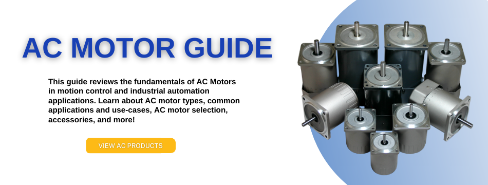
AC Motor Guide
Mar 2023 Nicole Jones
Table of Contents
What is an AC Motor?
An AC motor is an electric motor which converts AC (Alternating Current) into mechanical power. This mechanical energy is created from the force exerted by the rotating magnetic fields produced by the alternating current that flows through the motor's coils.
How does an AC Motor work?
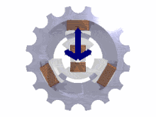
An AC motor consists of two main components: the stator and the rotor. The stator is the stationary part of the motor, consisting of several thin laminations wound with an insulated wire, forming the core. The stator is constructed with slots that hold the conductors (windings), which carry the current. These conductors are insulated from each other to prevent short-circuiting. The number of slots and windings are configured to a specific pole count; the lower the pole count, the higher the rated speed. Speed from an AC Motor is defined as RPM = 120*F/P where F is the frequency (Hz) of the supply voltage and P is the number of poles.
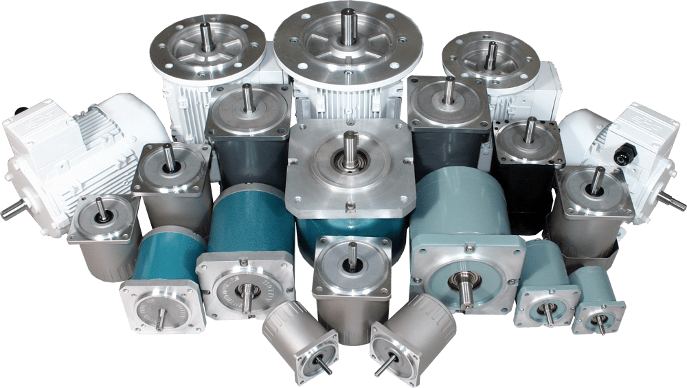
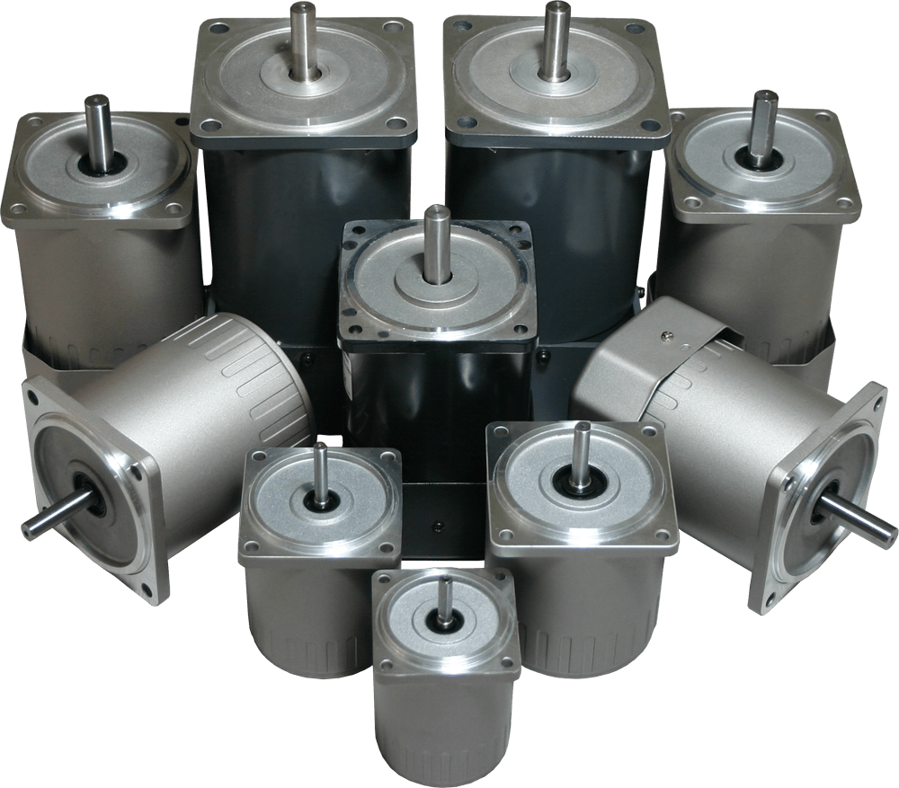
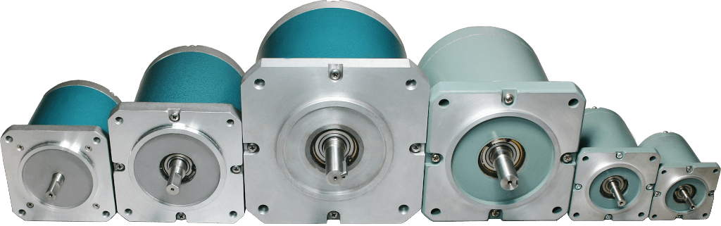
Three-Phase AC Motor
The rotor is connected to the shaft of the motor. The most common type of rotor used in an AC motor is the squirrel cage rotor, named after its resemblance to rodent exercise wheels. The rotor is balanced by bearings on the motor housing which surrounds the stator. Typically, motor housings are a steel constructed heat sink that reduces heat generation in the laminated windings and protects the windings and rotor from being damaged.
Types of AC Motors
There are two main types of AC motor:
- AC Induction (Asynchronous) Motor
- AC Synchronous Motor
AC Induction Motor
The fundamental operation of an AC induction motor (sometimes referred to as an asynchronous motor) relies on the principles of magnetism. A typical AC motor contains a coil of wire and two fixed magnets surrounding a shaft. When an electric (AC) charge is applied to the coil of wire, it becomes an electromagnet, generating a magnetic field. When the stator winding is supplied with electric energy, a magnetic flux is induced from the current flow.
In AC Induction Motors, current is only supplied to the stator. The rotor of an AC induction motor is designed to short the coil in the stator, which induces another magnetic flux in the rotor. The flux in the rotor will always have a delay relative to the stator flux, but will rotate with respect to the magnetic field. This causes torque to be applied to the shaft and causes the shaft to rotate. The difference between the rotation speeds of the rotor vs. the magnetic field of the stator is called slip.
AC Synchronous Motor
AC Synchronous motors do not depend on this induced magnetic flux in rotor and stator to operate. Instead, AC synchronous motors are constructed with magnets in the stator, which produce a rotating magnetic field. In a synchronous motor, current is supplied to the rotor, which also has a magnetic field, typically produced by a permanent magnet. Rotation is caused by interaction of the stator's magnetic field with the rotor's magnetic field.
Unlike an induction motor, the rotor in a synchronous motor will rotate with no lag or time delay. They are called synchronous because at steady state, the rotating speed of the rotor is equal to the speed of the rotating magnetic field in the stator. The rotation of the rotor is synchronized with the supply frequency.
The stator requires three-phase power (typically supplied by a VFD) for all three phases in the stator. Synchronous motors have an advantage over single-phase induction motors – with synchronous motors, the starting direction can be selected.
AC Motor Lifetime and Required Maintenance
Anaheim Automation AC motors have a typical service life of approximately 10,000 operating hours, given the motors are operating under proper conditions and in accordance with product specifications. AC motor lifespan will differ depending on manufacturer and operation.
Preventative maintenance is the key to a long-lasting AC motor system. Routine inspections should be implemented. During inspections, check the AC motor for dirt and corrosion. Dirt and debris can clog air passages and reduce airflow, ultimately reducing insulation life and leading to possible motor failure. When debris is not blatantly visible, check to ensure air flow is strong and steady. A weak or interrupted air flow could potentially point towards clogging. In moist, humid, or wet environments, check for corroded terminals in the conduit box and repair when necessary. Listen for excessive noise or vibration, and feel for excessive heat. This could indicate additional lubrication of the bearings is needed.
Note: Be cautious when lubricating the bearings as excessive lubrication may lead to dirt and oils clogging air flow. Be sure to locate and remove the source of heat for the motor to avoid system failure.
How Much do AC Motors Cost?
AC motors can be a reasonably cost-effective solution to your application requirements. The construction materials and motor design make AC motor systems an affordable solution. Since AC motors do not use brushes, the cost of the motor is lower and maintenance on the motor is drastically reduced. Single-phase AC motors do not necessarily require a driver to operate, allowing the user to save on initial setup costs.
How to Select an AC Motor
In order to select the appropriate AC motor for your application, you'll need to determine basic specifications. Calculate the required load torque and operating speed. Remember that induction and reversible motors cannot be adjusted; they require a gearhead. If this is required, select the appropriate gear ratio. Next determine frequency and power supply voltage for the motor. Typically, a three-phase AC motor is used in high power conversion applications, whereas a single-phase AC motor would be used in low-power conversion projects.
AC Motor Formulas


Wiring Your AC Motor
The following information is intended as a general guideline for wiring of the Anaheim Automation AC motor product line. Be aware that when you route power and signal wiring to a machine or system, radiated noise from the nearby relays, transformers, and other electronic devices can be inducted into the AC motor and encoder signals, input/output communications, and other sensitive low voltage signals, which can cause system faults.
Warning: To avoid the possibility of electrical shock, perform all mounting and wiring of the AC motor prior to applying power. Once power is applied, connection terminals may have voltage present. Dangerous voltages are capable of causing injury or death when present in the AC motor system. Use great caution when handling, wiring, testing, and adjusting during installation, set-up, tuning, and operation. Do not make extreme adjustments or changes to the AC motor system parameters, which can cause mechanical vibration and result in failure and/or power loss. Once the AC motor system is wired, do not run the system by switching the power supply on/off directly. Frequent power on/off switching will cause accelerated wear and aging of the system components, which will reduce the lifetime of AC motor system.
Strictly comply with the following rules when wiring your AC motor:
- Follow the wiring diagram associated with each AC motor and/or controller.
- Route high-voltage power cables separately from low-voltage power cables.
- Segregate input power wiring and AC motor power cables from control wiring and motor feedback cables. Maintain this separation throughout the wire run.
- Use shielded cable for power wiring and provide a grounded 360 degree clamp termination to the enclosure wall. Allow room on the sub-panel for wire bends.
- Make all cable routes as short as possible.
- Allow for adequate air-flow.
- Keep environment as clean as possible.
Mounting Your AC Motor
The following information is intended as a general guideline for the installation and mounting of the AC motor system:
Warning: Dangerous voltages capable of causing injury or death may be present in the AC motor system. Use extreme caution when handling, testing, and adjusting during installation, set-up, and operation.
It is very important that the wiring of the AC motor be taken into consideration upon installation and mounting. Any subpanel installed inside the enclosure for mounting system components, must be a flat, rigid surface free from shock, vibration, moisture, oil, vapors, or dust. Remember that the AC motor will produce heat during operation; therefore, heat dissipation should be considered in designing the system layout. Size the enclosure so as not to exceed the maximum ambient temperature rating. It is recommended that the AC motor be mounted in position as to provide adequate airflow. The AC motor should be mounted in a stable fashion, secured tightly.
Note: There should be a minimum of 10mm between the AC motor and any other devices.
In order to comply with UL and CE requirements, the AC motor system must be grounded in a grounded conducive enclosure offering protection as defined in standard EN 60529 (IEC 529) to IP55 such that they are not accessible to the operator or unskilled person. As with any moving part in a system, the AC motor should be kept out of the reach of the operator. A NEMA 4X enclosure exceeds those requirements providing protection to IP66. To improve the bond between the power rail and the subpanel, construct your subpanel out of zinc-plated (paint-free) steel. Additionally, it is strongly recommended that the AC motor system be protected against EMI. Noise from signal wires can cause mechanical vibration and malfunctions.
Environmental Considerations for an AC Motor
The following environmental and safety considerations must be observed during all phases of operation, service and repair of an AC motor system. Failure to comply with these precautions violates safety standards of design, manufacture and intended use of the AC motor. Please note that even a well-built AC motor system operated and installed improperly, can be hazardous. Precaution must be observed by the user with respect to the load and operating environment. The customer is ultimately responsible for the proper selection, installation, and operation of an AC motor and/or speed controller.
The atmosphere in which an AC motor is used must be conducive to good general practices of electrical/electronic equipment. Do not operate the AC motor system in the presence of flammable gases, dust, oil, vapor or moisture. For outdoor use, the AC motor must be protected from the elements by an adequate cover, while still providing adequate air flow and cooling. Moisture may cause an electrical shock hazard and/or induce system breakdown. Due consideration should be given to the avoidance of liquids and vapors of any kind in the operating environment. Contact the factory should your application require specific IP ratings. Install the AC motor in an environment which is free from condensation, electrical noise, vibration and shock.
Additionally, it is preferable to work with the AC motor system in a non-static protective environment. Exposed circuitry should always be properly guarded and/or enclosed to prevent unauthorized human contact with live circuitry. No work should be performed while power is applied.
DO NOT plug in or unplug when power is on. Wait for a minimum of 5 minutes before performing inspection work on the AC motor system after turning power off, because even after the power is turned off, residual electrical energy may remain in the capacitors of the internal circuit of the AC motor system.
Plan the installation of the AC motor in a system design that is free from debris, such as metal debris from cutting, drilling, tapping, and welding, or any other foreign material that could come in contact with system's circuitry. Failure to prevent debris from entering the AC motor system can result in damage and/or shock.
AC Motor Feedback
AC motors have two options for feedback controls. These options are either an AC motor resolver or an AC motor encoder. Both the AC motor resolver and the AC motor encoder can sense direction, speed, and the position of the output shaft. While both the AC motor resolver and AC motor encoder offer the same solution in multiple applications, they have important differences.
The AC motor optical encoder uses a shutter that rotates to disrupt a beam of light that crosses the air gap between a light source and the photo detector. The rotating of the shutter over time causes wear on the encoder. This wear reduces the durability and dependably of the optical encoder.
The type of application will determine whether a resolver or an encoder is preferable. AC motor encoders are easier to implement and more precise, so they should be the primary preference for any application. A resolver should only be chosen if required by the environment in which the system will be used.
What is an AC Motor Controller?
An AC controller (sometimes referred to as a "driver") is a device which controls the rotational speed of the AC motor. The AC motor receives power, which is ultimately converted by the AC controller into an adjustable frequency. This adjustable output allows the motor speed to be precisely controlled.
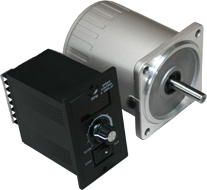
Components of an AC Speed Controller
Typically, an AC controller consists of three basic parts: the rectifier, inverter, and the DC link to connect the two. The rectifier converts AC input into DC (direct current), while the inverter switches the DC voltage to an adjustable frequency AC output voltage. The inverter can also be used to control output current flow if needed. Both the rectifier and inverter are directed by a set of controls to generate a specific amount of AC voltage and frequency to match the AC motor system at a given point in time.
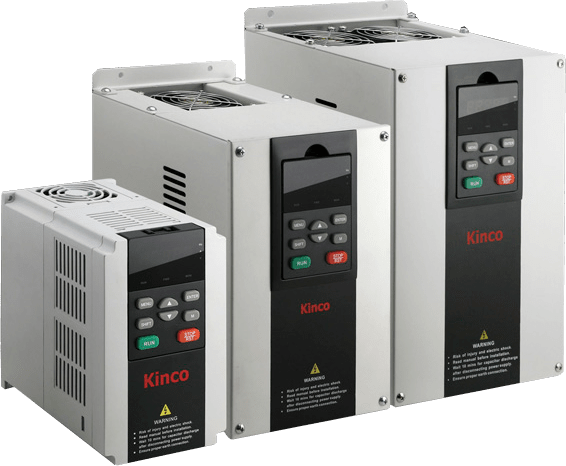
What is a Variable Frequency Drive?
Variable frequency drives are adjustable-speed drives used to control the speed of an AC motor. In order to control the motor's rotational speed, a VFD controls the frequency of the electrical power supplied to it. Adding a VFD to an application allows the motor speed to be adjusted in accordance with the motor's load, ultimately saving the system energy. Suitable for a myriad of applications, a VFD can be used for operating ventilation systems, pumps, conveyors and machine tool drives, and more.
Advantages of a Variable Frequency Drive:
- Process temperature can be controlled without a separate controller
- Low maintenance
- Increased lifespan for the AC motor and other system components
- Lower operating costs
- Equipment in the system that cannot handle excessive torque is protected
How Does a Variable Frequency Drive Work?
When voltage is applied to an AC motor, it accelerates the load and drops torque initially, keeping current especially high until the motor reaches full speed. A VFD eliminates excessive current, increasing voltage and frequency in a controlled manner as the motor starts up. This allows the AC motor to generate up to 150% of its rated torque, which could potentially be generated from the moment of startup, all the way up to full speed, without wasting energy.
A VFD converts power through three different stages. First, AC power is converted to DC power, followed by the switching on and off of the power transistors, causing a voltage waveform at the desired frequency. This waveform then adjusts output voltage according to the preferred designated value.
Components of a VFD System
Typically, a VFD system involves an AC motor, controller, and operator interface. A three-phase AC induction motor is most commonly used with a VFD because it offers versatility and cost-effectiveness in comparison to a single-phase or synchronous motor. Though they can be advantageous in some circumstances, VFD systems more often utilize motors that are designed for fixed-speed operation.
VFD operator interfaces allow for the user to adjust operating speed, as well as start and stop the motor. (One example of an operator interface is an HMI.) With an operator interface the user can switch and reverse between automatic control, or manual speed adjustment.
Types of Variable Frequency Drives
There are three common VFDs that offer both advantages and disadvantages depending on the application they are used for. The three common VFD designs used include: Current Source Inverter (CSI), Voltage Source Inverter (VSI), and Pulse Width Modulation (PWM). Each VFD consists of a Converter, DC Link and Inverter section, but the construction of each component varies between models and manufacturers. Although the sections of each VFD are similar, they require a variation in circuitry to supply the frequency and voltage to the motor.
Current Source Inverter (CSI)
A Current Source Inverter (CSI) is a type of VFD which converts incoming AC voltage and varies the frequency and voltage supplied to the AC induction motor. The general configuration of this type of VFD is like that of other VFDs in that it consists of a Converter, DC Link, and Inverter. The converter part of the CSI uses silicon-controlled rectifiers (SCRs), gate-commutated thyristors (GCTs) or symmetrical gate-commutated thyristors (SGCTs) to convert the incoming AC voltage to a variable DC voltage.
In order to maintain the correct voltage-to-frequency (Volt/Hertz) ratio, the voltage must be regulated by the correct sequencing of the SCRs. The DC link for this type of variable frequency drive uses an inductor to regulate the current ripple and to store the energy used by the motor. The inverter, which is responsible for converting the DC voltage back to an AC sine-like waveform, comprises of SCRS, gate turn-off thyristors (GTOs) or symmetrical gate-commutated thyristors (SGCTs).
These thyristors behave like switches which are turned on and off to create pulse width modulation (PWM) output that regulates the frequency and voltage to the motor. CSI variable frequency drives regulate current, and require a large internal inductor and a motor load to operate.
An important note about CSI VFDs – they require input and output filters due to high harmonics in the power input, and poor power factor. To work around this issue, many manufacturers implement either input transformers or reactors and harmonic filters at the point of common coupling (users electrical system connected to the drive) to help reduce the effects harmonics have on the drive system.
Of the common VFD drive systems, CSI VFDs are the only type that has regenerative power capability. Regenerative power capability means that power is driven back from the motor to the power supply and absorbed.
Advantages of CSI type VFD
- Regenerative power capability
- Simple circuitry
- Reliability (Current Limiting Operation)
- Clean current waveform
Disadvantages of CSI type VFD
- Motor cogging when PWM output is below 6 Hz
- Inductor used are large and costly
- Large power harmonic generation sent back into power source
- Dependent on motor load
- Low input power factor
Voltage Source Inverter (VSI)
The converter section of the VSI is similar to the converter section of the CSI in that the incoming AC voltage is converted into a DC Voltage. The difference from the CSI and VSI converter section is that the VSI uses a diode bridge rectifier to convert the AC voltage to DC voltage. The DC link of the VSI uses capacitors to smooth out the ripple in the DC voltage and to also store energy for the drive system. The inverter section is comprised of insulated gate bipolar transistors (IGBTs), insulated gate-commutated thyristors (IGCTs) or injection-enhanced gate transistors (IEGTs). These transistors or thyristors behave like switches which are turned on and off to create a pulse width modulation (PWM) output that regulates the frequency and voltage to the motor.
Advantages of VSI type VFD
- Simple Circuitry
- Can be used with applications requiring multiple motors
- Not dependent on load
Disadvantages of VSI type VFD
- Large power harmonic generation into power source
- Motor cogging when PWM output is below 6 Hz
- Non-Regenerative operation
- Low power factor
Pulse Width Modulation (PWM)
The Pulse Width Modulation (PWM) variable frequency drive is among the most commonly used controllers and has been proven to work well with motors ranging in size from 1/2HP to 500HP. Most PWM VFDs are rated for 230V or 460V, 3-phase operation, and provide output frequencies in the range of 2-400Hz.
Like the VSI VFD, the PWM VFD uses a diode bridge rectifier to convert the incoming AC voltage to a DC voltage. The DC link uses large capacitors to remove the ripple evident after the rectifier and creates a stable DC bus voltage.
The six-step inverter stage of this driver uses high power rated IGBTs which turn on and off to regulate the frequency and voltage to the motor. These transistors are controlled by a microprocessor or motor IC, which monitors various aspects of the drive to provide the correct sequencing. This produces a sine-like waveform output to the motor. Turning a transistor on and off helps create the sine-like wave output – by varying the voltage pulse width, you are obtaining an average power which is the voltage supplied to the motor . The frequency supplied to the motor is determined by the number of positive to negative transitions per second.
Advantage of PWM type VFD
- No motor cogging
- Efficiencies from 92% to 96%
- Excellent input power factor due to fixed DC bus voltage
- Low initial cost
- Can be used with applications requiring multiple motors
Disadvantages of PWM type VFD
- Non-Regenerative operation
- High frequency switching may cause motor heating and insulation breakdown
AC Motor Accessories
There is a vast selection of accessories for use with AC motors, including brakes, connectors, and cables. See Anaheim Automation's Accessories page for more details.
Our AC motor brakes operate on a 24VDC system. With a low-voltage design, these brakes are ideal for any holding applications that are susceptible to weak battery, brown out, or long wiring. AC motor cables can be custom made with the supplied AC motor connector to fit given specifications. Cables may also be purchased from Anaheim Automation.
AC Motors vs Brushless DC Motors
Advantages of AC Motors over BLDC Motors
AC motors offer exceptional starting torque, making them ideal for applications requiring enough torque upon startup to move a given load. On the other hand, brushless DC motors often require a gearbox in order to achieve enough torque at startup to successfully move a load. Additional advantages of AC Motors include:
- Low cost
- Long lifespan
- Highly efficient and reliable
- Simple design and construction
- Economical speed control
- Optimize motor-starting characteristics
- Lower maintenance than DC control
Disadvantages of AC Motors Compared to BLDC Motors
AC motors are built for torque, not for speed. Applications requiring high speeds are typically better served by selecting a BLDC motor, as they are more suited to providing torque at high speeds. Brushless motors also draw lower current, and can be easily adjusted to provide rotor position, starting direction, etc. AC motors also operate loudly, are large and heavy, and are not as efficient as BLDC motors when it comes to back-EMF. Other AC Motor disadvantages include:
- Frequency causes rotation slips (AC induction motors)
- Starting switch required (AC induction motors)
- Large amount of heat and harmonics generated during operation
Conclusion
AC and BLDC motors are each (sometimes exclusively) suited for differing applications. Determining whether to use one or the other in your system requires you to take into account the aforementioned points to select the most suitable unit. To learn more about BLDC Motors, refer to our Brushless DC Motor Guide.
AC Motor Applications
Due to their relatively low cost and durability, AC motors can be used in a number of industries and applications, such as:
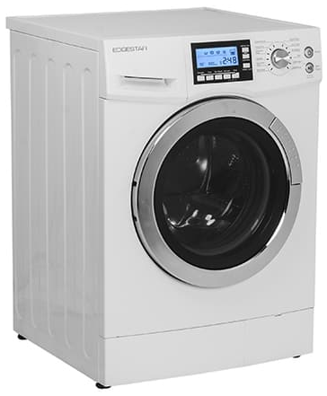
Consumer Goods
- Mixers
- Grinders
- Rotisserie ovens
- Power tools
- Disk drives
- Washing machines
- Audio turntables
- Fans
Industrial Applications
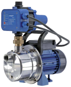
- Water pumps
- Mills
- Lathes
- Saws
- Punch presses/Chassis makers
- Blowers
- Conveyors
- Compressors
History of the AC Motor
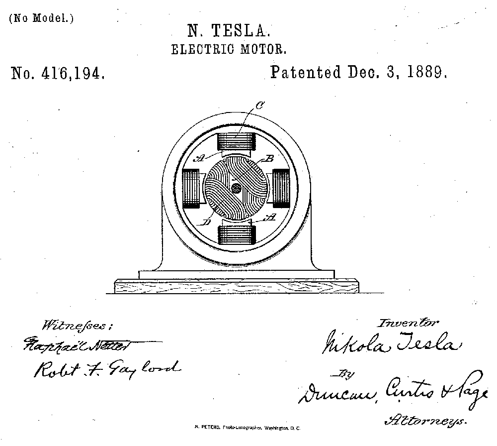
Nikola Tesla believed that motors did not need brushes for the rotor to commutate, determining that they could be induced by a rotating magnetic field. He had identified the use of alternating current which induced rotating magnetic fields. In 1888, Tesla invented the first AC induction motor, filing U.S. patent number 416,194 soon after and introducing a more reliable and efficient motor than its DC counterpart.
However, AC speed control proved to be a challenging task. In applications where precise speed control was required, the DC motor became preferred over the AC motor because of its efficient and economical means of accurately controlling speed. It wasn't until the 1980s that AC speed control became a viable competitor. Over time, AC drive technology eventually transformed into an inexpensive and reliable competitor to the traditional DC control. Today, an AC controller is capable of speed control with full torque attained from 0 RPM through the maximum rated speed.
AC motors are known for their simple design, ease of use, rugged construction, and cost-effectiveness in many different applications. Advances in technology have allowed manufacturers to build on Tesla's idea, and have allowed a great versatility in the speed control of the AC induction motor. From a simple phase control to more robust closed-loop systems that use vector oriented field controls, the AC motor has greatly advanced over the last one hundred and twenty years.
AC Motor Troubleshooting
Please note: Technical assistance regarding its AC motor product line, as well as all products manufactured or distributed by Anaheim Automation, is available at no charge. This assistance is intended to help the customer in selecting Anaheim Automation products for a specific application. In all cases, determination of fitness of the products in a specific system design is solely the customers' responsibility. While every effort is made to offer solid advice regarding the AC Motor product line, as well as other motion control products, and to produce technical data and illustrations accurately, such advice and documents are for reference only, and are subject to change without notice.
The following steps may be taken to troubleshoot an AC Motor and Controller system:
- Step 1: Check the motor's smell. If there is a burning smell, replace the motor immediately.
- Step 2: Check the motor's input voltage. Ensure wires are not damaged and the proper power supply is connected.
- Step 3: Listen for loud vibration or squeaking noises. Such noises may indicate damaged or worn-out bearings. If possible, lubricate the bearings, otherwise replace the motor completely.
- Step 4: Check for overheating. Use compressed air to rid the motor of debris. Allow the motor to cool, then restart.
- Step 5: AC Motors that make an effort to start, but fail, may be a sign of a bad starting capacitor. Check for any signs of leaking oil, and replace the capacitor if this is the case.
- Step 6: Ensure the application the motor is rotating is not locked up. Do this by disconnecting the mechanism and try running the motor by itself.
Note: Modifying any Anaheim Automation product will void the warranty. If you need help troubleshooting an Anaheim Automation component, or would like to request an RMA, please Contact Us before making any changes. Please refer to our Terms and Conditions and Repairs and Returns FAQs for more information.
AC Motor Glossary
AC Motor – An electric motor that is driven by an alternating current, as opposed to a direct current.
Alternating Current – Electric charge that frequently reverse in direction (opposite of direct current, with charge in only one direction).
Centrifugal Switch – The electric switch that controls the rotational speed of a shaft, operating off of the centrifugal force generated from the shaft itself.
Gear Ratio – The ratio at which the motor's speed is reduced by the gearhead. The speed at the output shaft is the gear ratio multiplied by the motor speed.
Inverter – The device that converts direct current to alternating current. Reverse of the Rectifier.
Induction Motor – Can be referred to as asynchronous motor; type of AC motor where electromagnetic induction supplies power to the rotor. Slip is required to produce torque.
No Load Speed – Typically lower than synchronous speed, it is the speed when the motor is not carrying a load.
Rated Speed – The speed of the motor at rated output power. Typically the most sought-after speed.
Rectifier – The device that converts alternating current to direct current within a motor. They can be utilized as a component in a power supply, or can detect radio signals. Typically rectifiers may consist of solid state diodes, mercury arc valves, or other substances. Reverse of the inverter.
Rectification – The process by which alternating current is converted to direct current by means of a rectifier within an AC motor.
Split Phase Induction Motor – Motors that can generate more starting torque by using a centrifugal switch combined with a special startup winding.
Stall Torque – Given a particular voltage and frequency, the maximum torque in which the motor can run. Exceeding this amount will cause the motor to stall.
Starting Torque – The torque that instantly generated as the motor starts. The motor will not run if friction load exceeds torque.
Static Friction Torque – When a motor is stopped by a brake for example, it is the torque output needed to hold a load as the motor stops.
Synchronous Motor – Unlike the induction motor, it can produce torque at synchronous speed, without slip.
Synchronous Speed – Indicated by speed per minute, it is the intrinsic factor determined by number of poles and line frequency.
Variable Speed Drive – Equipment used to control electric power frequency supplied to an AC motor, in order to manage its rotational speed.