We use cookies to make your experience better. To comply with the new e-Privacy directive, we need to ask for your consent to set the cookies. Learn more.
Encoders Guide
Encoders Guide
Mar 2023 Nicole Jones
Table of Contents
What is an Encoder?
The basic definition of an encoder is a sensor of mechanical motion which generates digital signals in response to motion. Encoders are able to provide motion control system users with information concerning position, velocity and/or direction.

Dual-Shaft Motor Without Encoder

Dual-Shaft Motor With Encoder
Every control system leverages some form of sensor feedback. For example, an oven uses a thermometer to sense when to turn on or turn off a heating element. Disturbances in system processes are measured by a sensor and “fed back” to the PID controller to make the necessary changes to ensure process stability. A disturbance could be as simple as opening the oven door or placing a frozen food item on the oven racks. The heating element will have to turn on again to overcome the change in temperature. In motion control systems, the most common sensor used is called an encoder.
Encoders provide a measured feedback of mechanical motion (displacement or velocity) to a motion controller.

Encoder Feedback Process
In this guide we will discuss:
Motion Types
- Rotary
- Linear
Technology
- Optical
- Magnetic
- Capacitive
Functionality
-
Incremental
- Single-Ended
- Differential
- HTL (Push-Pull)
- TTL
-
Absolute
-
Analog
- 0-5V, 0-10V
- 4-20mA
-
Communication
- Fieldbus (Profibus, CANopen, DeviceNet, Interbus, SAE J1939 (automotive)
- Ethernet (IP, EtherCAT, ProfiNet, Modbus
- Serial (SSI, SPI, RS485)
- BiSS
-
Analog
- Commutation
Features
- IP65
- Flanged
- Shaft Mounted
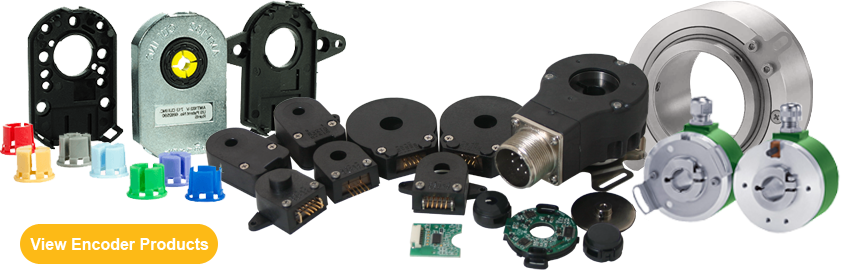
Types of Encoders
Depending on your application requirements, certain types of encoders may be more suitable than others. Anaheim Automation offers an array of rotary incremental encoders such as optical, magnetic, and capacitive types, as well as linear magnetic incremental encoders.
Optical encoders are a cost-effective industry-wide standard that provide precision and accuracy, but may be more susceptible to environmental factors such as heat, shock, dust/dirt ingress. Optical encoders are available in absolute, incremental, and commutation configurations.
Magnetic encoders are more robust, can operate in conditions with ingress of dirt, dust, oil, and other environmental factors, but do not provide as much resolution as their optical counterparts. Magnetic encoders are available in both rotary and linear configurations.
Linear encoders are designed to measure linear motion, rather than rotary motion. They are typically used with linear components, such as blocks and rails. They are less robust and more suited to applications in an environment free of dust and debris.
Capacitive encoders combine the best aspects of both optical and magnetic rotary encoders in one rugged, reliable device, but are not suited for large motor shafts (larger than 8mm diameter). Capacitive encoders are available in both incremental and absolute configurations. Read more about capacitive encoders in our Capacitive Encoders Guide.
Incremental Rotary Encoders
An incremental rotary encoder is also referred to as a quadrature encoder. This type of encoder utilizes sensors that use optical, mechanical or magnetic index counting for angular measurement.

Single-Ended Incremental Rotary Encoder
How Do Incremental Optical Encoders Work?
Incremental rotary encoders utilize optical light to detect position/velocity via a transparent disk which contains opaque sections that are equally spaced to determine movement. A light emitting diode is used to pass through the glass disk and is detected by a photo detector. This causes the encoder to generate a train of equally spaced pulses as it rotates. The output of incremental rotary encoders is measured in pulses per revolution which is used to keep track of position or determine speed.

Pulse Train Produced from Incremental Encoder
A single-channel output is commonly implemented in applications in which direction of movement is not significant, similar to how a tachometer would work. Instances in which direction sensing is important, a 2-channel, quadrature, output is used. The two channels, A and B, are commonly 90 electrical degrees out of phase and the electronic components determine the direction based off the phase relationship between the two channels. The position of an incremental encoder is calculated by adding up all the pulses by a counter. By knowing how many pulses the specific encoder outputs in a revolution, the final count divided by the pulses per revolution will yield the number of revolutions performed by the motor.
A setback of the incremental encoder is count loss, which occurs during power loss. When restarting, the equipment must be referenced to a home position to reinitialize the counter. However, there are some incremental encoders, like those sold at Anaheim Automation, which come equipped with a third channel called the index channel. The index channel produces a single signal pulse per revolution of the encoder shaft and is often used as a reference marker. The reference marker is then denoted as a starting position which can resume counting or position tracking.
Note: Incremental rotary encoders are not as accurate as absolute rotary encoders due to the possibility of interference or a misread.
Physical Properties of Incremental Optical Encoders

Internal Components of an Incremental Optical Encoder
The key components of an optical incremental encoder are a glass disk, LED (light emitting diode), and a photo detector. The transparent disk contains opaque sections which are equally spaced to deflect light while the transparent sections allow light to be passed through. An optical encoder utilizes a light emitting diode which shines light through the transparent portions of the disk. The light that shines through is received by the photo detector which produces an electrical signal output.

Incremental Optical Encoders Components Diagram
Absolute Optical Encoders
An absolute encoder contains components similar to those found in incremental encoders. They implement a photodetector and LED light source, but instead of a disk with evenly spaced lines, an absolute encoder uses a disk with concentric circle patterns.
How Do Absolute Optical Encoders Work?
Absolute encoders utilize a stationary mask in between the photo detector and the encoder disk.

Absolute Encoder Disk with Concentric Circle Pattern
The output signal generated from an absolute encoder is in digital bits which correspond to a unique position. The bit configuration is produced by the light which is received by the photodetector when the disk rotates. The light configuration received is translated into gray code. As a result, each position has its own unique bit configuration.
Commutation Encoders
A commutation encoder contains the same fundamental components as incremental encoders but with the addition of commutation tracks alongside the outer edge of the disk for U/V/W output.

Commutation Encoder
How Do Optical Commutation Encoders Work?
Commutation encoders operate the same way incremental optical encoders do, tracking position using optical light and a slotted encoder disk.
The outer part of the encoder disk includes commutation tracks which provide a controller with information on the exact position of the motor poles, so that the proper controller input can be supplied to the motor. The commutation tracks of the encoder read the motor position and instruct the controller as to how to provide efficient and proper current to the motor to cause rotation. Commutation output for U/V/W can be in the form of differential output or open-collector (manufacturer dependent).
Magnetic Rotary Encoder
Magnetic encoders are a type of rotary encoder that use sensors to identify changes in magnetic fields from a rotating magnetized wheel or ring.
How Do Magnetic Rotary Encoders Work
The rotor turns with the shaft and contains alternating evenly spaced north and south poles around its circumference. The sensor detects these small shifts in the position N>>S and S>>N. There are many methods of detecting magnetic field changes, but the two primary types used in encoders are Hall Effect and Magneto resistive. Hall Effect sensors work by detecting a change in voltage by magnetic deflection of electrons. Magneto resistive sensors detect a change in resistance caused by a magnetic field.

Encoder Rotor with North & South Poles
Physical Properties of Magnetic Rotary Encoders
A magnetic encoder consists of three main components: the disk, the sensors, and the conditioning circuit. The disk is magnetized and includes poles around its edge. Sensors identify changes in the magnetic field as the disk rotates, converting this information to a digital signal. The conditioning circuit multiples, divides, or interpolates the signal to generate the required output.

Magnetic Rotary Encoder
Hall-Effect Sensing
The sensor produces and processes Hall-Effect signals producing a quadrature signal as is common with optical encoders. The output is generated by measuring magnetic flux distributions across the surface of the chip. The output accuracy is dependent on the radial placement of the IC with respect to the target magnet. The chip face should be parallel to the magnet so the magnet to sensor air gap is consistent across the sensor face.
Magnetic encoders avoid the three vulnerabilities that optical encoders face:
- Seal failures which permit the entry of contaminants
- The optical disk may shatter during vibration or impact
- Bearing failures
Magnetic devices designed effectively eliminate the first two failure modes and offer an opportunity to reduce bearing failures as well. Magnetic encoders do not make errors due to contamination because their sensors detect variations in magnetic fields imbedded in the rotor and oil, dirt and water do not affect these magnetic fields.
Hall-Effect sensors generally have lower cost and are less precise than magnetic resistive sensors. This means that Hall-Effect sensors, when used in an encoder produce more "jitter", or error in the signal caused by sensor variations.
Linear Encoders
A linear encoder is a sensor, transducer or reading-head linked to a scale that encodes position. The sensor reads the scale and converts position into an analog or digital signal that is transformed into a digital readout. Movement is determined from changes in position with time. Both optical and magnetic linear encoder types function using this type of method. However, it is their physical properties which make them different.
How Do Optical Linear Encoders Work?
The light source and lens produce a parallel beam of light which pass through four windows of the scanning reticle. The four scanning windows are shifted 90 degrees apart. The light then passes through the glass scale and is detected by photosensors. The scale then transforms the detected light beam when the scanning unit moves. The detection of the light by the photosensor produces sinusoidal wave outputs. The linear encoder system then combines the shifted signals to create two sinusoidal outputs which are symmetrical but 90 degrees out of phase from each other. A reference signal is created when a fifth pattern on the scanning reticle becomes aligned with an identical pattern on the scale.
How Do Magnetic Linear Encoders Work?
A magnetic linear encoder system uses a magnetic sensor readhead and a magnetic scale to produce TTL or analog output for channels A and B. As the magnetic sensor passes along the magnetic scale, the sensor detects the change in magnetic field and outputs a signal. This output signal frequency is proportional to the measuring speed and the displacement of the sensor. Since a linear encoder detects change in the magnetic field, the interference of light, oil, dust, and debris have no effect on this type of system; therefore they offer high reliability in harsh environments.

Linear Encoder Read Head and Magnetic Scale
Physical Properties of Linear Encoders
The key components of magnetic linear encoders are a scanning unit, sensor, transducer or readhead, paired with a transmissive or reflective scale, which encodes position. The scale of a linear encoder is generally made of glass and mounted to a support and the scanning unit contains a light source, photocells, and a second glass piece called the scanning reticle. Collectively, the linear encoder is able to convert motion into digital or analog signals to determine the change in position over time.
How are Encoders Controlled?
A rotary encoder is controlled through the rotation the shaft it is mounted to. The shaft comes into contact with a hub inside of the encoder. The speed at which the encoder rotates depends on the speed of the shaft the encoder is connected to. Anaheim Automation's optical and magnetic rotary encoders are powered from a single +5VDC power source, and is able to sink and source 8mA each.
Linear encoders are controlled through the linear motion of the block as it moves along the linear guide rail. The speed at which the encoder travels will be the speed at which the block travels. Anaheim Automation's magnetic linear encoders are powered by either a +5VDC line driver or +10-30VDC push-pull power supply (model dependent).
Where are Encoders Used?
Encoders have become a vital source for many applications requiring feedback information. Whether an application is concerned with speed, direction or distance, an encoder's vast capabilities allow users to utilize this information for precise control. With the emergence of higher resolutions, ruggedness, and lower costs, encoders have become the preferred technology in more and more areas. Today, encoder applications are all around us. They are used in printers, automation, medical scanners, and scientific equipment.
Anaheim Automation's cost-effective encoder product line is a wise choice for applications requiring feedback control. Anaheim Automation's customer for the encoder product line is diverse: industrial companies operating or designing automated machinery involving food processing, labeling, cut-to-length applications, conveyor, material handling, robotics, medical diagnostics, CNC machinery, and more.
Encoders Are Used in Many Industries
Encoders have become an essential component to applications in many different industries. The following is a partial list of industries making use of encoders:
- Automotive – The automotive industry utilize encoders as sensors of mechanical motion may be applied to controlling speed
- Consumer Electronics and Office Equipment – In the consumer electronics industry, encoders are widely used office equipment such as PC-based scanning equipment, printers, and scanners
- Industrial – In industrial applications, encoders are used in labeling machines, packaging and machine tooling with single and multi-axis motor controllers. Encoders can also be found in CNC machine control
- Medical – In the medical industry, encoders are utilized in medical scanners, microscopic or nanoscopic motion control of automated devices and dispensing pumps
- Military – The military also uses encoders in their application of positioning antennae
- Scientific Instruments – Scientific equipment implements encoders; for example, in the positioning of an observatory telescope
Applications for Encoders
An encoder can be used in applications requiring feedback of position, velocity, distance, etc. The examples listed below illustrate the vast capabilities and implementations of an encoder:
- Robotics
- Labeling Machines
- Medical Equipment
- Textiles
- Drilling Machines
- Motor Feedback
- Assembly Machines
- Packaging
- X and Y Indication Systems
- Printers
- Testing Machines
- CNC Machines
How to Select an Encoder
First, you will need to determine the type of encoder that will best suit your requirements:
What type of motion do you intend to measure – rotary or linear? What type of environment will the encoder be used in? Optical rotary encoders are more suited for clean environments where they will not be subjected to dust, oil, debris, etc. If your application is measuring rotary movement and is located in an environment where these factors will need to be considered, you may be better served using a more rugged magnetic or capacitive encoder. Anaheim Automation's magnetic linear encoder sensors and scales are resistant dust, debris, and liquids, with the read head sensors being IP67 rated.
Selecting an Optical Rotary Encoder
There are several important criteria involved in selecting the proper optical rotary encoder:
- Output
- Desired Resolution (CPR)
- Noise and Cable Length
- Index Channel
- Cover/Base
Output
The output is dependent on what is required by the application. There are two output forms: incremental and absolute. Incremental output options include: Single-Ended / Non-Indexed, Single-Ended / Indexed, Differential / Non-Indexed, Differential / Indexed Incremental output forms take form of squarewave outputs. For an application requiring an incremental encoder, the output signal is either zero or the supply voltage. The output of an incremental encoder is always a squarewave due to the switching of high (input voltage value) and low (zero) signal value. Absolute encoders operate in the same manner as incremental encoders, but have different output methods. The resolution of an absolute encoder is described in bits. The output of absolute encoders is relative to its position in a form of a digital word. Instead of a continuous flow of pulses as seen by incremental encoders, absolute encoders output a unique word for each position in form of bits. Equivalent to 1,024 pulses per revolution, an absolute encoder is described to have 10 bits (210 = 1024).
Desired Resolution (CPR)
The resolution of incremental encoders is frequently described in terms of cycles per revolution (CPR). Cycles per revolution are the number of output pulses per complete revolution of the encoder disk. For example, an encoder with a resolution of 1,000 means that there are 1,000 pulses generated per complete revolution of the encoder. Anaheim Automation's optical rotary encoders are available in 2 to 10,000 CPR.
Noise and Cable Length
When selecting the proper encoder for any application, the user must also take into account electromagnetic noise and cable length. Longer cable lengths are more susceptible to noise. It is crucial to use proper cable lengths to ensure the system functions correctly. It is recommended to use shielded, twisted-pair cables with preferably low capacitance value. The rating for capacitance value is normally in capacitance per foot. The importance of this rating is for well-defined squarewave pulse outputs from the encoder rather than "jagged" or "saw-toothed" like pulses due to the interference of noise. Differential signals are best for incremental encoders that have to handle noise or long cable runs (6’+).
Index Channel
The index channel is an optional output channel which provides a once per revolution output pulse. This pulse allows for the user to keep track of position and establishes a reference point. This output channel is extremely valuable for incremental encoders when an interruption of power occurs. In instances with a power failure, the last sustained index channel can be used as a reference marker for a restarting point. Therefore, when such an occurrence takes place, an index channel can prove to be quite valuable in applications utilizing incremental encoders. Absolute encoders do not have an issue with losing track of position in power loss situations, because every position is assigned a unique bit configuration.
Optical Encoder Cover and Base Options
Cover and base options are considerations for specific application requirements. Enclosed cover options help protect the encoder from dust particles. Base options play a significant role in large vibration environments. Such mounting options are transfer adhesives which stick directly on the back of the encoder to the mounting surface, molded ears for direct mounting. Anaheim Automation also offers various base options for mounting purposes.
How to Select a Magnetic Rotary Encoder
When considering your whether to use a magnetic rotary encoder in your design, ask the following questions:
Does your application require a bearingless encoder design?
While an encoder with bearings is the most common solution, systems with high levels of shock and vibration, as well as high-speed systems, can be hard on the bearings found in these encoders.
Is space limited?
Because magnetic rotary encoders are typically compact in design, they may be more suited to applications where space is limited. For example, robotics applications typically have a limited amount of space available, but still require precise and reliable motor feedback.
Will dust, dirt, and oil be present?
One of the most important factors in determining the type of encoder your application requires is the environment in which the system will be used. Optical rotary encoders are highly susceptible to the ingress of dust and debris. Their optical discs can be damaged by these particles, which can make the encoder less accurate and may even result in the complete failure of the encoder. Ruggedly designed magnetic encoders do not rely on optical discs, so the ingress of dust, dirt, and oils is less of a concern. For further protection, many of our magnetic encoders are available with heavy-duty seals (IP65 and IP66). These encoders are splash proof, making them an excellent choice for wash down applications.
To determine which magnetic rotary encoder is best suited to your application, establish the following:
Incremental or Absolute Output?
Anaheim Automation offers a wide range of magnetic rotary encoders available in both incremental and absolute configurations.
Incremental output options include: Single-Ended / Non-Indexed, Single-Ended / Indexed, Differential / Non-Indexed, Differential / Indexed incremental output forms take form of squarewave outputs. For an application requiring an incremental magnetic rotary encoder, the output signal is either zero or the supply voltage. The output of an incremental encoder is always a squarewave due to the switching of high (input voltage value) and low (zero) signal value.
Absolute magnetic rotary encoders operate similarly to incremental encoders, but with different output methods. The resolution of an absolute encoder is expressed in bits, and the output is relative to its given position. Instead of a continuous flow of pulses as with incremental encoders, absolute output has a unique signal for each position. An absolute encoder would be 10 bits, rather than 1,024 PPR as with an incremental encoder.
Desired Resolution (CPR)
Anaheim Automation's incremental magnetic rotary encoders are available in resolutions of 20 to 10,000 CPR, and our absolute magnetic rotary encoders are available in resolutions from 8 to 17 Bit/Multi-turn.
Noise and Cable Length
Minimize cable lengths to reduce electrical noise. Using proper cable lengths will ensure the system functions correctly. Using shielded, twisted-pair cables with low capacitance value is also recommended.
Index Channel
Our incremental magnetic rotary encoders include an optional index channel, an output channel which provides an output pulse for each revolution, which allows the user to track position and establish a reference point. This output channel, in instances with a power failure, enables the user to reference the last sustained index channel as an indicator for a restarting point.
Magnetic Rotary Encoder Cover and Mounting Options
Each of our series offers a variety of mounting and cover options. Enclosed cover options help protect the encoder from dust particles. Base options play a significant role in large vibration environments. Anaheim Automation also offers various base options for mounting purposes. Browse our complete magnetic rotary encoder line to view options for each series.
How to Select a Magnetic Linear Encoder
Magnetic linear encoders are frequently used in applications with linear components, such as guide rails and blocks. However, they are also suitable for rotary applications when the scale is mounted in a ring formation. As the magnetic sensor travels along the magnetic scale or ring, it detects the displacement and outputs a TTL signal. The frequency of the output signal is proportional to the measuring speed and displacement of the sensor.
Anaheim Automation offers a line of versatile IP67-rated incremental magnetic linear encoders, with sensor and scale components sold separately. Consider the following when selecting a linear encoder:
Desired Sensor Resolution
The higher the resolution, the greater the accuracy of the sensor reading will be. Our magnetic linear encoder sensors are available in resolutions of 5, 10, 25, or 50µm.
Output and Power Supply
What is your desired output circuit? Our linear encoders are offered in line-driver (AB, /AB), push-pull (AB, /AB), or push-pull (AB). The line-driver configuration utilizes a +5VDC ±5% power supply, and both push-pull configurations use a +10 - 30VDC power supply.
Index
An optional index channel is available, either as an every 5mm pole pitch or a unique reference signal for each pole.
Scale Length and Accuracy
ENC-MT50 flexible magnetic scales have an adhesive backing and can be easily mounted to nearly any metals, ceramics, and other surfaces. These scales are resistant to oil, chemicals, and debris, which ensures an accurate reading by the magnetic sensor. The magnetic scale consists of alternating north and south pole magnets which are placed at fixed distances. This is called the pole pitch. The overall length of the incremental magnetic scale ENC-MT50 should exceed the measuring length by at least 10mm (0.4”) on each side. Scales are available in lengths of 100 to 2000mm, with accuracies of ±8µm/m, ±35µm/m.
Accessories
Linear encoder accessories such as reference pole markers and wipers are available. The reference pole support should only be used with the unique reference signal index.
How to Install an Encoder
Following mounting best practices ensures that the feedback loop will accurately provide data, enabling the system to perform at maximum efficiency. To this end, Anaheim Automation offers a series of encoder adders, where we mount the encoder for you, hassle free! We will also mount any of our other encoders to any of our dual-shaft motors for a nominal fee.
The best mounting method depends on the type of encoder being used:
Shaft Encoders
Shaft encoders are mounted to a motor shaft using a centering tool to align the hole of the encoder to the shaft using a flexible coupling. The coupling connects the encoder shaft directly to the motor shaft with set screws, securing the encoder and shielding it from shock, vibration, and electrical noise (EMI), as well as compensating for shaft misalignment and ensuring the encoder does not shift position on the motor shaft.
Hollow-Shaft Encoders
The process of encoder selection and installation is typically simple for hollow-shaft encoders. By matching the sizes of the motor shaft and encoder bore hole diameter, users can ensure a perfect fit. Hollow-shaft encoders are mounted directly to the motor shaft without the use of a coupling. They are affixed to the motor face with a flexible tether or torque arm to prevent the encoder from turning with the motor shaft. Instead, bearings within the encoder allow the optical disc to rotate with the motor shaft independently of the housing.
Linear Encoders
Linear encoders are used to measure linear movement, as opposed to rotary encoders which measure rotary movement.

Mounted Linear Encoder
The read head, or sensor, is typically mounted to a linear guide block using a bracket. The magnetic scale has an adhesive backing allowing it to be mounted along the rail or track. As the block moves down the track, the sensor uses the magnetic strip to detect its location.
Refer to the individual spec sheet of the product you are installing for detailed set-up instructions, or contact our applications engineers for direct assistance. Our video tutorials offer step-by-step instructions on installing several examples of Anaheim Automation's optical rotary encoders:
Required Maintenance for an Encoder
Encoders require very little maintenance due to their ruggedness and reliability. However, it is recommended to minimize an encoder's exposure to dust particles or debris and also, unless designed for exposure to water, moisture, especially for optical encoders. Additionally, under duress of shock and vibrations the discs within optical encoders may become scratched, resulting in encoder failure. If such an event occurs, the disc may need to be replaced to provide accurate readings.
Environmental Considerations for an Encoder
The following environmental and safety considerations must be observed during all phases of operation, service and repair of an encoder. Failure to comply with these precautions violates safety standards of design, manufacture and intended use of an encoder. Please note that even with a well-built encoder, products operated and installed improperly can be hazardous. Precaution must be observed by the user with respect to the load and operating environment. The customer is ultimately responsible for the proper selection, installation, and operation of the encoder.
The atmosphere in which an encoder is used must be conducive to good general practices of electrical/electronic equipment. Do not operate an optical encoder in the presence of flammable gases, dust, oil, vapor or moisture, as they are susceptible to damage from these environmental factors, whereas magnetic or capacitive types are not.
For outdoor use, the encoder must be protected from the elements by an adequate cover, while still providing adequate air flow and cooling. Moisture may cause an electrical shock hazard and/or induce system breakdown. Due consideration should be given to the avoidance of liquids and vapors of any kind. Contact the factory should your application require specific IP ratings. It is wise to install the encoder in an environment which is free from condensation, dust, electrical noise, vibration and shock.
Additionally, it is preferable to work with encoders in a non-static, protective environment. Exposed circuitry should always be properly guarded and/or enclosed to prevent unauthorized human contact with live circuitry. No work should be performed while power is applied. Don't plug in or unplug the connectors when power is ON. Wait for at least 5 minutes before doing inspection work on the encoder after turning power OFF, because even after the power is turned off, there will still be some electrical energy remaining in the internal circuit of the encoder circuitry.
Plan the installation of the encoder in a system design that is free from debris, such as metal debris from cutting, drilling, tapping, and welding, or any other foreign material that could come in contact with the circuitry. Failure to prevent debris from entering the encoder can result in damage and/or shock.
Lifetime of an Encoder
The lifetime of an encoder is dependent on various factors such as encoder type, environmental exposure and application use. By limiting the exposure of the encoder to electrical equipment, temperatures above recommended values, condensation, and vibration and shock, and using the encoder as directed by the manufacturer can extend the lifetime of an encoder.
Encoder Accessories
Along with the encoder line, Anaheim Automation carries a comprehensive line of single-ended and differential encoder cables with four, six, and eight leads, cable lengths up to 16 feet, programming cables for capacitive encoders, encoder centering tools, and reference pole markers and wipers for our linear magnetic encoders. Additionally, Anaheim Automation offers an extended line of stepper, brushless, and servo motors.
Advantages and Disadvantages of Encoders
Advantages
- Highly reliable and accurate
- Low-cost feedback
- High resolution
- Fuses optical and digital technology
- Can be incorporated into existing applications
- Compact size
Disadvantages
- Subject to magnetic or radio interference (Magnetic Encoders)
- Direct light source interference (Optical Encoders)
- Susceptible to dirt, oil and dust contaminants
Formulas for Encoders
The relationship between the encoder CPR frequency and the speed of the motor (RPM) is given by the following equation:

RPM = Revolutions per Minute
CPR = Cycles per Revolution
The formula for distance conversion is as follows:

Distance Conversion Formula

Pulses per Revolution
Troubleshooting
Please note: Technical assistance regarding its Encoder line, as well as all the products manufactured or distributed by Anaheim Automation, is available at no charge. This assistance is offered to help the customer in choosing Anaheim Automation products for a specific application. However, any selection, quotation, or application suggestion for an Encoder, or any other product, offered from Anaheim Automation's staff, its representatives or distributors, are only to assist the customer. In all cases, determination of fitness of the custom Encoder in a specific system design is solely the customers' responsibility. While every effort is made to offer solid advice regarding the Encoder product line, as well as other motion control products, and to produce technical data and illustrations accurately, such advice and documents are for reference only, and subject to change without notice.
Problem: No output
Solution: No output may be a result of various factors. Steps can be taken to ensure the proper functionality of the encoder. No mechanical movement results in any signal being output from the encoder. To correct this issue, observe if the encoder is rotating. Verify all wring between the encoder and the driver/controller is correct and the appropriate voltage supply is used. Having loose connections or improper voltage supply may not allow the encoder to function properly. Finally, ensure the correct signal type (e.g. open collector, pull-up, line driver or push-pull) is being used for your application. If the problem persists, swap encoders, if possible, to determine if the encoder is the issue.
Problem: Unable to find index pulse
Solution: The index pulse, or reference marker, is a once per revolution output of an encoder and is best found using an oscilloscope. Verify all the wiring between the encoder and the driver/controller is correct and the appropriate voltage supply is used. If that does not solve the issue, try lowering the RPM of the motor, as the driver/controller may not be able to identify the index pulse at very high RPM values.
Problem: Count output indicates incorrect direction
Solution: If the count output indicates an incorrect direction then check for the wire configuration. See if any wires are reversed. If they are reversed, simply swap wires.
Note: If your application is using index, reversing the wire configuration causes the reference alignment to also change. If so, please make the appropriate changes to your application.
Problem: Encoder is not rotating
Solution: When encoders are exposed in open environments, dust and debris particles may accumulate around the shaft. Simply clean the exposed area and ensure that there are not objects obstructing the encoder from rotating.
Problem: Noise Interference
Solution: To improve the noise immunity of encoders it is strongly advised that no other electrical equipment be nearby or be kept at a fair distance. Encoder cables should also be shielded and proper wires should be grounded to minimize electrical noise.
Problem: Distorted or incorrect output
Solution: Distorted or incorrect output can be caused by any combination of loose wiring connections, encoder output not compatible with driver/controller, electrical noise or improper alignment. Check for wire connections, compatibility issues with the encoder and the driver/controller, alignment of the encoder and the shaft to solve this issue.
Glossary
Absolute Encoder – provides the shaft position in a bit configuration and is able to maintain or provide absolute position even after instances of power loss/failure.
Accuracy – difference in distance between the theoretical and the actual position.
Cycles Per Revolution (CPR) – Cycles per revolution are the number of output pulses per complete revolution of the encoder disk.
Encoder – is a sensor of mechanical motion that generates digital signals in response to motion.
Incremental Encoder – device that provides a train of pulses due in response to mechanical motion. The output of this encoder is in form of a squarewave.
Index – a separate output channel which provides a single pulse per shaft revolution. It can be used to establish a reference or marker for a starting position.
Interpolation – is the method of increasing the resolution of an encoder. This method allows for the encoder to produce a higher resolution output without increasing the overall size of the disk and encoder.
Line Driver – is a sourcing output. This means that when in ‘ON' state the line driver will supply VCC and in the ‘OFF' state the driver will float. A sinking input is required for line driver applications.
Open Collector – is a sinking output. In the ‘OFF' state, an open collector will be grounded and in the ‘ON' state, the open collector will float. A sourcing input is required for open collector applications.
Pulses Per Revolution (PPR) – the total number of pulses produced per full revolution of the encoder shaft.
Push-pull – is a combination between a line driver and an open collector. In the ‘OFF' state it will be grounded and in the on ‘ON' state it will supply VCC
Quadrature Encoder – two output channels which are out of phase by 90 electrical degrees. From the phase difference, the direction of rotation can also be determined.
Resolution – number of line increments on a disk. Resolution for incremental encoders is often referred to as cycles per resolution and for absolute encoders it is in terms of bits.
Single Channel Encoder – has only one output channel and is used in speed applications.
Squarewave – a repetitive waveform corresponding to high and low signals.