We use cookies to make your experience better. To comply with the new e-Privacy directive, we need to ask for your consent to set the cookies. Learn more.
Brushless Motors
- Home
- Brushless DC
- Brushless Motors
Brushless Motors | Anaheim Automation, Inc.
Information
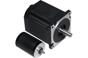
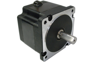
Anaheim Automation's budget-friendly BLDC Motors are meticulously engineered to meet the demands of both high-volume OEM applications and low-volume projects. Our motors are available in a selection of frame sizes, ranging from 0.3" to 3.4" in diameter, with power capacities from under 1 Watt to an impressive 1,000 Watts.
Need a custom motor solution? Our contract manufacturing services include specialized motor shafts and windings, private-labeling, footprint-matching, and more. Customers can also complete their system with value-added motor accessories, including mounted encoders, brakes, connectors, cables, and gearboxes. Contact our engineers to discuss your application today.
Note: For specials and customization, a minimum purchase may be required.
FAQ
What are brushless DC motors?
Brushless DC motors, or "BLDC motors," are synchronous electric motors powered by DC (direct current) voltage. They are electronically commutated without
brushes, hence the name "brushless motors." Brushless DC motors consist of a fixed armature along with permanent magnets which rotate, hall sensors, stator
windings, rotor magnet North and South, Hall sensor magnets, an accessory shaft, and a driving end of the shaft.
How do brushless DC motors work?
Brushless DC motors have an electronic commutation system, no brushes, and no mechanical commutators. This allows brushless electric motors to operate at higher
speeds than their brushed counterparts. There can also be a different number of poles on the stator for each motor.
How are brushless DC motors controlled?
Most BLDC motors require a controller or driver to run. There are many different types of controls and drives designed for various applications. Many come with
adjustable options, and Anaheim Automation can offer custom designs specific to a client's application. These devices are commonly referred to as "Electronic Speed
Controllers," or ESCs. In a brushless DC controller or BLDC driver, either a Hall Effect Sensor or the back
EMF (Electromotive Force) will be used to run the motor. The Hall Effect uses three Hall sensors within the motor to detect the position of the rotor. This method is
primarily used in applications requiring speed detection, positioning, current sensing, and proximity switching. The magnetic field will change in response to the
transducer which varies its output voltage. Because the sensor operates as an analog transducer, a feedback loop is created by directly returning a voltage.
The distance between the Hall plate and a known magnet, as well as the relative position of the magnet, can be determined with the internal Hall sensors. A Hall sensor can also act as an on/off switch in a digital mode and when combined with the proper circuitry.
Back EMF, also known as the Counter-Electomotive Force, is caused by a changing electromagnetic field. In brushless electric motors, the back EMF is a voltage which occurs where there is motion between the external magnetic field and the armature of the motor. In other words, the voltage is developed in an inductor by an alternating current or pulsating current. At every moment, the polarity of the voltage is the reverse of the input voltage. This method is commonly used to measure the motor's position and speed indirectly.
What is the primary difference between a brush DC motor and a brushless DC motor?
Brush, or "brushed," DC motors use commutation brushes which periodically change the direction current flows to maintain torque. Because of the eventual
wearing down of these brushes, a brush DC motor will require more maintenance and will have a shorter life than brushless DC motors. Instead of brushes, BLDC motors use
hall sensors at the back end of the motor. These hall sensors output high-low pulses when they detect a change in the magnetic field. For this reason, brushless DC motors
require more complex controllers, such as VSDs (variable speed drives). Additionally, since BLDC motors do not use brushes for commutation purposes, they are far more
efficient, require very low maintenance, and have a longer life than brushed DC motors.
Where are BLDC motors used?
Brushless DC motors are popularly used in many industries and applications. For example:
Consumer Electronics
Brushless DC motors have monopolized many areas of the consumer electronics industry and are used in many different locations, such as in computer hard drives and CD/DVD/Blu-ray players. Brushless DC motors are also used to operate the small cooling fans located in electronic equipment. Cordless power tools also utilize BLDC motors because the need for increased efficiency of the BLDC motor allows for long periods of use before needing to recharge the battery. Furthermore, direct-drive turntables for analog audio disks use low-speed, low-power brushless electric motors.
BLDC motors have also increased in popularity among the radio controlled (RC) cars, buggies, and trucks, where sensor-type BLDC motors allow the position of the rotor magnet to be detected. Many BLDC motors feature upgrades and replaceable parts like sintered neodymium-iron-boron (rare earth magnets), replaceable motor timing assemblies, and ceramic bearings. As a result, these BLDC motors are quickly ascending to the top of the list as the preferred motor choice for electric on and off-road RC racers. BLDC motors are low-maintenance and provide high reliability and power efficiency ~ most BLDC motors offer an efficiency rating of 80% or more.
Transportation
Electric and hybrid vehicles use high power brushless DC motors that are essentially AC synchronous with permanent magnet rotors. Brushless DC motors are used in Segway and Vectrix-Maxi-Scooters also. Electric bicycles sometimes build brushless DC motors into their wheel hubs, with the stator solidly fixed to the axle and magnets attached to and rotating with the wheel. These electric bicycles have a standard bicycle transmission with pedals, sprockets, and chain that, if needed, can be pedaled along with or without the use of the brushless DC motors.
HVAC
It has become a popular trend to switch from AC motors to BLDC motors (EC) because of the dramatic reduction in power needed o run them, compared with the typical AC motor. Although shaded-pole and permanent split capacitor motors were the primary fan motor of choice, many fans today are being run by BLDC motors. Some use BLDC motors simply to increase system efficiency as a whole. Certain HVAC systems use ECM motors (electronically commutated BLDC motors). In particular are the HVAC systems which feature load-modulation and/or variable-speed. BLDC motors not only have higher efficiency, but also a built-in microprocessor that allows for better airflow control, programmability, and serial communication.
Model Engineering and Hobbyists
The most popular motor option for model aircraft today are BLDC motors. The BLDC motors are available in a wide array of sizes, and have a favorable power to weight ratios. BLDC motors have transformed the market of electric-powered flight. The introduction of BLDC motors has displaced the use of almost all brushed electric motors in model aircraft and helicopters. Modern batteries and BLDC motors allow model airplanes to vertically ascend, versus gradually climb. Small glow fuel internal combustion engines that were used in the past are no comparison to the silent and clean BLDC motors.
Medical Applications
Brushless DC Motors have become popular amongst the medical industry for their long-lasting and low-maintenance design. Used in medical equipment, brushless DC motors have a life expectancy of 10,000 hours, whereas brushed DC motors have only a 2,000-5,000 hour lifespan. Brushless DC motors also have a top speed that is not limited by a large number of poles. It wasn't until the cost of these brushless DC Motors decreased, that they became a viable option for most medical applications. These motors are far less expensive, a primary reason they are appealing for medical equipment design.
Sleep apnea can also be treated with the help of brushless DC motors. Treatment for the disorder requires the use of Positive Airway Pressure (PAP) respirators. The PAP respirator is attached to a special breathing mask that the patient must wear to breathe through while sleeping. Within the respirator is a blower fan that pressurizes the air mask according to the patients breathing pattern. As the patient inhales, the blower fan speeds up to allow more air to reach the lungs. Conversely, when the patient exhales, the blower fan slows down to reduce the amount of air the patient breathes out.
Brushless DC motors never need to operate underneath the minimum threshold speed of the drive, so they are the perfect power source for blower fans. Furthermore, there is no risk for any sudden changes in load. Low-noise-level standards force hospital equipment to be as quiet as possible, thus making brushless DC motors a prime candidate due to how silently they operate. Brushless DC motors can operate accurately at high speeds while still maintaining low sound levels. Therefore, they can be used both in hospitals and in patients' homes. It is the absence of a commutator and brushes in brushless DC motors that removes even more of the motor noise.
Additional industries may include:
- Instrumentation
- Appliances
- Automotive
- Industrial Automation Equipment
- CNC Machinery
- Semiconductor
- Packaging Equipment
- Aerospace
- Military and Surveillance, and more
How do you select a brushless DC motor?
When selecting brushless DC Motors, you'll need to take a few factors into consideration:
What is my application? What are my specifications? How much do I want to spend? Which controller/driver is most suitable?
These questions will help to narrow down your selection. You will then need to determine all specifications, known ones along with possible ones. For example, do you need a specific frame size, weight, power, speed, length, etc.? Each motor listed will offer specifications inherent to that particular model, such as rated voltage, rated torque, torque constant, back EMF constant, and rated power which all related to the appropriate driver. Select a driver based on the rated power, rated voltage, and the current required to run your motor given your application requirements. Keep in mind there are many different motors and driver/controllers to choose from. If you require assistance with making a selection, our applications engineers will be happy to assist you.
What are the Advantages and Disadvantages for Brushless DC Motors?
Some of the Advantages of brushless DC motors include, but are not limited to:
- Higher Speed Ranges
- High Dynamic Response
- Long Operating Life
- Better speed versus torque characteristics
- Noiseless operation
- High efficiency
- Higher cost than brushed DC motors
- Additional system wiring is required to power the electronic commutation circuitry
- More complex to operate: motion controllers/drivers are needed to operate brushless DC motors
Helpful Information
Brushless DC Motor Basics
Typically when the term "brushless" is used it refers to brushless DC motors, rather than referring to a general control term meaning "a feedback loop
used to position the product, including brushless DC motor items." Brushless DC motors differ from other controlled motors because they are controlled by a time-based
derivative commonly known to as the PID loop. Brushless DC motors must be capable of changing the velocity (rate of change of position) of the output shaft because of the
time-based derivative.
Brushless DC motors can provide a more efficient, reliable, and compact motor that can be used in a variety of ways. Essentially, brushless DC motors are synchronous electric motors which are powered by a DC power source. An electric commutation circuit replaces the standard commutator and brush assembly found in the brushed DC motor. Brushless DC motors and brushed DC motors are essentially polar opposites - while the windings of brushed DC motors rotate around the rotating shaft or armature, the brushless DC motors have windings that are attached to the motor housing. The magnets of the brushed DC Motors attach to the motor housing, while brushless DC motors magnets are affixed to the rotor.
Commutation is the process of reversing the polarity of the phase currents in the windings of the motor at an exact time that will produce continuous rotational torque. If commutation did not occur, the magnets and magnetic fields would lock the rotating shaft in place by aligning themselves. The appropriate reversal time is crucial; the brushless DC motor shaft must continue spinning, and it does so as a result of the changing polarity of the windings. The primary way brushless DC motors and a brushed DC motors differ is in their methods of commutation. Brushed DC motors use brushes and a commutator that acts as an electromechanical switch to connect the windings in the proper polarity. With brushless DC motors, electronic switches take the place of the mechanical switch, controlling the timing of the polarity-reversal via an electrical circuit. Usually, BLDC motors sense rotor position and control the electronic drive of brushless DC motors by using Hall-effect devices (HFD). However, because motor back- EMF can be monitored, the HFD can be eliminated to create a sensorless Brushless DC motors drive.
BLDC Motor Cost
The cost of BLDC motors varies widely - from as low as twenty dollars to several hundred dollars. Cost largely depends on the size and capabilities of the brushless
motors themselves.
Basic Types of Brushless DC Motors
All brushless DC motors are permanent magnet motors. There are also two basic types labeled as "trapezoidal motors" or as "sine wave motors." A
trapezoidal motor is a DC servo motor and a sine wave motor closely resembles an AC synchronous motor.
Physical Properties of Brushless DC Motors
Brushless DC motors have the external physical appearance of a stationary 3-phase permanent magnet device, which is known as the "stator." The rotating
armature is located within the device, and is called the "rotor." Brushless DC motors can be constructed in many different configurations. One configuration is
known as the "Inrunner" type, where the permanent magnets are a part of the rotor and three stator windings surround the rotor. Another configuration is the
"Outrunner" type, where the radial relationship between the coils and magnets is reversed. The stator coils form the core of the motor, while permanent magnets
spin within an overhanging rotor surrounding the core.
BLDC Motor Construction
The Stator
The stator of a brushless DC motor consists of stacked steel laminations with slots cut into them where the windings are. The stator of a BLDC motor is similar to that of an AC motor, however the windings are different. There are three stator windings in each brushless motor hooked up in either a Delta or star configuration. Each of these windings have multiple coils that are constructed to connect together to form a winding. Anaheim Automation typically has six coils per brushless DC motor, which are combine to form a three-phase winding. There are usually an even number of poles.
Mainly there two types of stator windings, sinusoidal and trapezoidal. The difference in the stator windings is identified in the interconnection of the coils of the stator windings which result in a different type of back EMF. The trapezoidal variant delivers its back EMF in the shape of a trapezoid. Each sinusoidal variation gives its BLDC motor a back EMF that matches the current. The faulted also is used as the shape of the sinusoid and a trapezoid. The difference between the two brushless DC motors is that the sinusoidal motors have smoother output torque than that of trapezoidal motors. The stator winding can be wound for multiple voltages. This can be customized for almost any distinct application.
The Rotor
The rotor is made up of permanent magnets and normally has between two and eight poles. The magnets are bonded onto the rotor core in alternating North and South pole fields. Permanent magnet rotors are generally constructed with ferrite magnets. If a higher power density is needed in an application, rare earth magnets are generally used instead. Higher power density means that the brushless DC motors can put out much more torque in a smaller volume, which is helpful to manufacturers who are continuously pushed to provide smaller and smaller packages. The ferrite magnets are less expensive, but the flux density is lower than that of the rare earth magnets. The price of rare earth magnets is also lower now than it has been in the past. Rare earth magnet types: Neodymium (Nd) Samarium Cobalt (SmCo) rather than Neodymium, Ferrite, and Boron (NdFeB) alloy.
Housing
Brushless DC motors can be manufactured with a housing-free design, where the laminations are exposed and coated with a rust-proof paint. Other brushless DC motors are housed in an extrusion, or in an aluminum or steel cylindrical housing where the laminations of the stator are secured.
Wiring
The general information provided in the following paragraphs is designed to be a guideline for wiring the Anaheim Automation Brushless DC Motors. System faults and communication errors can result from routing power and signal wiring on a machine or system, also radiated noise from the close by relays, transformers, and electronic devices can be inducted Brushless DC Motors and encoder signals, other sensitive low voltage signals, and input/output communications.
Mounting
The following information is designed as a overall guideline for the installation and mounting of brushless DC motor systems.
WARNING - Dangerous voltages are capable of causing injury or death may be present in the Brushless DC Motors systems. Use extreme caution when handling, testing, and adjusting during installation, set-up, and operation.
It is very important that the wiring of BLDC motors and controllers be taken into consideration prior to installation and mounting. Subpanels installed inside the enclosure for mounting Brushless DC Motors systems components, must be a flat, rigid surface, and must be free from shock, vibration, moisture, oil, vapors, or dust.
Remember that Brushless DC Motors and controllers will produce heat during work. Be sure to take heat dissipation into consideration when designing the system layout. In order to stay below the maximum ambient temperature rating, size the enclosure accurately and make sure that BLDC controller will be mounted in a position that will provide adequate airflow. The BLDC motor needs to be mounted in a stable fashion and tightly secured.
NOTE: There must be a minimum of 10mm in between the brushless DC controllers and any other devices mounted in the system/electric panel or cabinet. In order to comply with CE and UL standards, the brushless DC system must be grounded in a grounding-conducive enclosure offering protection as defined in standard EN 60529 (IEC 529) to IP55 such that they are not accessible to the operator or any unskilled person. As with any active part in a system, the BLDC motor should always be kept out of the reach of the operator. A NEMA 4X enclosure surpasses those requirements providing protection to IP66. To improve the bond between the power rail and the subpanel, construct your subpanel out of zinc-plated (paint-free) steel. Additionally, it is strongly suggested that the BLDC controllers be protected against electrical noise interferences, because noise from signal wires can cause mechanical vibration and malfunctions.
Brushless Motor Accessories
At Anaheim Automation, we provide various accessories for our brushless DC motors, including brakes,
encoders, speed
read outs, connectors,
cables, and drivers.
Brakes can be pre-mounted to any dual-shaft BLDC Motor, and will be delivered to the customer attached to the rear shaft of the motor. Our Brushless DC Motors brakes have a low voltage (24VDC) design for applications that are susceptible to brown out, weak batteries, or long wiring runs. When electric power is applied to the brake, the armature is drawn by the electromagnetic force in the magnet body assembly, which overcomes the spring action, allowing the friction disc to rotate freely. When electrical power is interrupted, the electromagnetic force is removed and the pressure spring mechanically forces the armature plate to clamp the friction disc between itself and the pressure plate.
Brushless motor cables and connectors, upon request, can also be pre-mounted the motor as a value-added assembly, or can be ordered separately from Anaheim Automation.
Encoder Feedback
For low-speed products, the use of an encoder is recommended for feedback rather than Hall sensors. The number of counts per revolution for the Hall sensor can only
be as large as the number of poles multiplied by the number of Hall Sensors. When operating the brushless motor, the BLDC controller can utilize the higher count to its
advantage. The brushless controller can utilize the additional CPR data at its disposal for more precise velocity control. The higher the resolution of the encoder, the
more fine the control over the motor will be. Although encoders are more expensive than Hall sensors, the precise level of control still comes at a lower cost than
alternate technologies such as AC motors, Servo motors, or Synchronous motors.
Hall Sensor Feedback
Hall Sensors create feedback when rotating the brushless DC motor's sequentially energized stator windings. In order to understand the next winding that would need
to be energized in the proper sequence, the controller needs to know the rotor position. The rotor position is sensed by the Hall sensors embedded in the back end cap of
the BLDC motor's housing. Brushless DC motors utilize three Hall sensors, which are divided by either 60° or 120°. Each Hall sensor is typically mounted on a PC
board and fastened to the back end cap on the non-driving end of the brushless DC motor. Hall sensors sense either the rotor magnet or external magnet placed in the back
of the shaft, and send off a signal signifying whether or not a North or South Pole passes the sensors. Using each signal from the sensors, the controller can easily
maintain the motor's velocity.
Brushless Motor Life Cycle
The key difference between brushless motors and their predecessors is the process of commutation. Newer brushless DC motors are commutated electrically using Hall
elements, counter EMF counter, or encoder feedback. BLDC motors are very useful and cost-effective both in design and construction, however there are some factors which
can negatively affect the life expectancy of the motor:
Key Points to Remember:
Bearing failure and lack of lubrication are major factors when it comes to brushless DC motors failing. As a result, manufacturers now use industrial grade components which results in some brushless electric motors with lifetimes in excess of 20,000 hours or more! Integrated into these brushless DC motors are permanently lubricated ball bearings that use special grease, thus eliminating the need for re-lubrication.
IMPORTANT NOTE: Non-approved lubricants are not recommended for the Brushless DC motor components. Use of such lubricants could potentially shorten the life of the BLDC motor.
Temperature also plays a key role in the lifespan of brushless electric motors. The motor casing in particular must ensure that the heat generated in the brushless motor's windings will be dispelled. BLDC motors could face severe damage if the maximum heat limit is exceeded. BLDC motor performance directly correlates with the maximum possible rotor temperature, ambient temperature, and duty cycle. As temperature increases, the winding resistance increases and magnetic forces decrease, ultimately causing brushless motors to perform less efficiently.
When brushless DC motors are run at high continuous loads, heat sinking and forced air-cooling can considerably lower operating temperatures. It is highly recommended that all of these factors be taken into consideration when designing and installing motion control systems that include brushless DC motors.
Customization
Anaheim Automation offers a wide variety of standard brushless DC motors. However, OEM customers with medium to large quantity requirements may prefer to have a
motor customized or modified to meet their exact design specifications. Oftentimes the customization is as simple as shaft modification, the addition of a brake, an oil
seal for an IP65 rating, adjusted mounting dimensions, different wire colors, or a custom label. At other times, a customer may require that a motor be designed to meet
ideal specifications such as speed, torque, and/or voltage.
Anaheim Automation's BLDC motor customer base is diverse, including: companies running or designing automated machinery or functions that involve food, cosmetics or medical packaging, labeling or tamper-evident requirements, assembly, conveyor, material handling, robotics, special filming and projection effects, medical diagnostics, inspection and security devices, pump flow control, metal fabrication (CNC machinery), equipment upgrades, and more. Many OEM customers request private-labeling of their custom designs to ensure that they maintain the loyalty of their own customers for servicing, replacements and repairs.
Buyers appreciate the convenience Anaheim Automation's capacity as a one-stop-shop, as well as the cost savings of a custom brushless motor custom design. Engineers value the creativity, system efficiency, and flexibility that Anaheim Automation presents for their BLDC product line. Our standard brushless motors are known for their rugged construction, excellent performance, and cost-effectiveness.
A considerable portion of our sales results from our ability to surpass customer expectations in fulfilling their custom requirements. While a good portion of Anaheim Automations Brushless DC Motors sales consist of custom, special, or private-labeling requirements, we take pride in our stock of standard units, located in Anaheim, California, USA. To make the customization process affordable, a minimum order quantity (MOQ) and/or a Non-Recurring Engineering (NRE) fee may be required. All sales of customized or modified brushless DC motors are Non-Cancelable-Non-Returnable, and a NCNR Agreement must be signed by the customer at the time the order is placed. The NCNR may be required to be renewed with each purchase request.
All sales, including custom designs, are pursuant to Anaheim Automation's standardized Terms and Conditions, which take precedence over any other expressed or implied terms, including but not limited to any implied warranties.
PLEASE NOTE: Technical support regarding its Brushless DC Motors, or any and all other products manufactured or distributed by Anaheim Automation, will be offered at no charge. This assistance is provided to assist the customer in choosing Anaheim Automation products for a specific application. However, any application, selection, or quotation recommendation for any product provided by Anaheim Automation staff, distributors, or representatives is provided solely to assist the customer. In all cases, the customer is solely responsible for the determination of fitness of the standard or custom product for a given system design. While every effort is made to offer solid advice regarding our products, and to provide accurate technical data and illustrations, please note that such advice and documents are for reference only, and are subject to change without notice.
Safety
Use extreme caution when testing, handling, adjusting, and wiring during tuning, set-up, installation, and operation. Brushless DC motors systems, when operated at
high voltages, are capable of causing injury or death. To avoid the risk of electrical shock, perform all mounting and wiring of the Brushless DC Motors and controllers
system prior to applying power. Once power is applied, connection terminals may have voltage present. To prevent mechanical vibration which can lead to system failure
and/or loss, never make extreme changes or adjustments to the BLDC motor system's parameters. Do not directly turn the power supply from the Brushless DC Motors
Controllers on or off while the Brushless DC Motors are wired. Frequent switching the power on and off will also decrease the lifetime of the Brushless Electric Motors
systems by aging the internal components.
Be sure to strictly comply with the following rules:
NOTE: Factory made cables are ideal for use in our Brushless DC Motors and driver systems. These cables are purchased separately, and are designed to minimize EMI. These cables are suggested over customer-built cables to enhance system performance and to produce additional safety for the Brushless DC Motors system and the user.
Be sure to strictly comply with the following rules:
- Follow the Wiring Diagram with each Brushless DC Motors
- Route high-voltage power cables independently from low-voltage power cables.
- Segregate input power wiring and Brushless DC Motors power cables from control wiring and Brushless DC Motors feedback cables as they leave the Brushless DC Motors controller. Maintain this separation throughout the wire run.
- Use shielded cable for power wiring and provide a grounded 360 degree clamp termination to the enclosure wall. Enable room on the sub-panel for wire bends.
- Make all cable routes as short as possible.
NOTE: Factory made cables are ideal for use in our Brushless DC Motors and driver systems. These cables are purchased separately, and are designed to minimize EMI. These cables are suggested over customer-built cables to enhance system performance and to produce additional safety for the Brushless DC Motors system and the user.
Environmental Considerations for BLDC Motors
The following environmental and safety considerations must be observed during all phases of operation, service and repair of a BLDC motor system. Failure to
comply with these precautions violates safety standards of design, manufacture and intended use of the BLDC motor and controller. Please note that even well-built BLDC
motor and controller products, when operated and installed improperly, can be hazardous. Precautions must be observed by the user with respect to the load and operating
environment. The customer is ultimately responsible for the proper selection, installation, and operation of the BLDC motor system.
The atmosphere in which brushless motors are used must be conducive to general good practices of electrical/electronic equipment. Do not operate the brushless electric motor in the presence of flammable gases, dust, oil, vapor or moisture. For outdoor use, the motor and controller must be protected from the elements by an adequate cover while still providing adequate air flow and cooling.
Moisture may cause an electrical shock hazard and/or induce system breakdown. Due consideration should be given to the avoidance of liquids and vapors of any kind. Contact the factory should your application require specific IP ratings.
Install the BLDC motor and controller in an environment which is free from condensation, electrical noise, vibration, and shock. Be certain the area is free from debris, such as metal debris from cutting, drilling, tapping, and welding, or any other foreign material that could come in contact with circuitry. Failure to prevent debris from entering the brushless DC motor system can result in damage and/or shock. Additionally, it is preferable to work with the brushless DC motor and controller system in a non-static protective environment.
Exposed circuitry should always be properly guarded and/or enclosed to prevent unauthorized human contact with live circuitry. No work should be performed while power is applied. Don t plug in or unplug the connectors when power is ON. Wait for at least 5 minutes before doing inspection work on the BLDC motor system after turning power OFF, because even after the power is turned off, there will still be some electrical energy remaining in the capacitors of the internal circuit of the brushless DC motor controller.
History of Brushless DC Motors
Although brushless DC motors have been common in commercial use since 1962, the first BLDC motors appeared during the 1800s. This was made possible by the conversion
of electrical energy into mechanical energy by electromagnetic means, which was demonstrated in 1821by British scientist Michael Faraday.
In 1827, Hungarian physicist Ànyos Jedlik began experimenting with devices he called electromagnetic self-rotors. At the time, they were used solely for instructional purposes. In 1828, he demonstrated the first device to contain the three main components of practical direct current DC motors: the rotor, commutator, and stator. The magnetic fields of both the revolving and stationary components were produced by currents flowing through their windings, and the DC motors did not contain permanent magnets at the time.
William Sturgeon, another British scientist, invented the first commutator-type direct current electric motor capable of turning machinery in 1832. Americans Thomas and Emily Davenport built a commutator-type direct current electric motor with the intention of commercial use following Sturgeon’s progress, patenting their work in 1837. These early BLDC motors were used in printing presses and powered machine tools. They were said to have achieved up to 600 revolutions per minute (RPM). The motors were initially unsuccessful in the commercial field due to the high costs of the primary battery power and the lack of a practical commercial market for BLDC motors at that time.
Modern BLDC motors were accidently invented in 1873 by Zénobe Gramme. He then created the Gramme Machine, the first electric motor to be successful in the commercial industry. A non-sparking motor capable of constant speed under variable loads was the first practical, modern form of brushless DC motors were invented in 1886 by Frank Julian Sprague.
brushless dc electric motor, brushless electric motor, brushless motor, bldc motor, ip65 bldc motor, brushless dc motor, IP65 Brushless Motor, IP65 Brushless Motors, IP65 Brushless DC Motors, IP65 Brushless DC Motor