We use cookies to make your experience better. To comply with the new e-Privacy directive, we need to ask for your consent to set the cookies. Learn more.
Stepper Motors
Stepper Motors | Anaheim Automation, Inc.
Information
Anaheim Automation offers the most comprehensive line of Stepper Motor products available from a single source.
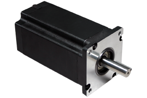
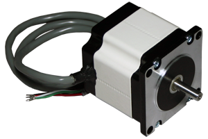
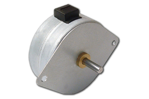
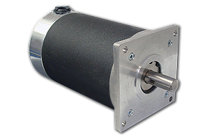
Shop our selection of High-Torque Stepper Motors, "Legacy" Round-Bodied Stepper Motors, Permanent Magnet (PM) Stepper Motors, and Specialty Stepper Motors such as 0.9° step-angle, IP65-Rated, and Stepper Motors with Integrated Drivers and Stepper Motors with Integrated Drivers/Controllers/Indexers. Our Step Motors range from the smallest NEMA 08 frame size with torque starting at 2.5 oz-in to the largest NEMA 42 frame size with up to 5,700 oz-in of torque.
Anaheim Automation can typically cross-reference stepping motors from other manufacturers with units from our product line, including obsolete products, often at significantly lower prices. Custom motor windings, shaft modifications, conduit boxes, and value-added encoder, brake, gearbox, connector, and cable options are available upon request.
Note: For higher IP ratings, or for assistance with selecting the appropriate unit for your project, please contact our applications engineers to discuss your requirements.