We use cookies to make your experience better. To comply with the new e-Privacy directive, we need to ask for your consent to set the cookies. Learn more.
Linear Actuator Guide
Linear Actuator Guide
Dec 2022
Table of Contents
What is a Linear Actuator?
The term "linear actuator" covers a broad range of products. A linear actuator is a mechanical device that converts energy (power from air, electricity or liquid) to create motion in a straight line, contrasted with circular motion of a conventional electric motor. It can also be used to apply a force. Types of motion include: blocking, clamping, ejecting, lifting, descending, pushing or pulling.
Basic Design of a Linear Actuator
As mentioned earlier, the term "linear actuator" covers a broad range of products; each sub-category looks and operates differently. In the majority of linear actuator designs, the basic principle of operation is that of an inclined plane. Simply stated, the threads of a lead screw act as a continuous ramp that allows a small rotational force to be used over a long distance to accomplish movement of a large load over a short distance.
How Does a Linear Actuator Work?
All linear actuators depend on an external, non-linear force to drive some kind of a piston back and forth. However, different types of linear actuators work in different ways. A ‘piston’ is defined as a sliding piece which is moved by or against fluid, air pressure, or electricity. It usually consists of a short cylinder fitting within a cylindrical vessel along which it moves back and forth. For example: in steam engines, motion is created by steam, and pumps transmit motion to a fluid.
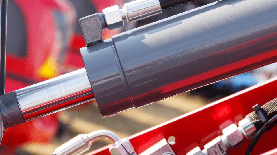
Piston or actuator of hydraulic machinery
Hydraulic pump actuators, for example, depend on a hydraulic pump to compress and decompress the two sides of a piston in order to push it back and forth. The piston is attached to an external shaft, so the shaft moves with it. On the other hand, a wax motor linear actuator uses an electric current to melt a block of wax, causing it to expand. As the wax expands and contracts with varying electrical currents, a plunger that is pressed against it moves back and forth in a linear motion.
Linear Actuator Power and Operational Options:
There are many options regarding the linear actuator driving force: Manual mechanical methods include the lead screw systems of vises and clamps, and levers found in manual juicers or can crushers. Cylinders with pistons powered by compressed air are used to move parts of machines. Hydraulic cylinders with pistons provide large forces and strokes for construction equipment such as shovels, lifts and jacks, and short throw cylinders for braking systems. Solenoid coils, which are short throw electromagnetic linear actuators, turn switches and valves on and off in addition to locking and unlocking doors. Linear progressions of electromagnetic motor poles are used for trams, people movers, and material conveyors. Self-contained linear actuator motors are also available.
What is a Linear Actuator Used For?
Linear actuators are used in industrial automation and machinery, machine tools, computer peripherals such as disk drives and printers, home automation, packaging, assembly, electronic manufacturing, data storage, laser processing, and test and inspection. Linear actuators are typically used in applications along with motors, valves, pumps, switches, dampers, and in many other places where linear motion is required. Linear actuators are also used for medical imaging and diagnostics, solar, farming, construction, automotive, and robotics applications.
Actuators working in a CNC machine
Linear actuators are used in nearly every type of electrical device that requires linear motion. Power drills, pumps, and other industrial appliances often rely on linear actuators to move other objects. Linear actuators are also used in some types of motors, and are often used in the robotics industry to provide robots with motor skills. In fact, a simple piston inside of an electric motor or fuel-injection engine uses linear motion, and therefore, acts as a linear actuator.
Basic Variations of Linear Actuators
Many variations of the basic linear actuator design have been created throughout time. Most focus on providing general improvements such as a higher mechanical efficiency, speed, or load capacity. There is also a large engineering movement towards linear actuator miniaturization. It is seen by some manufacturers that the smaller the linear actuator, the better. This does not necessary equate to cost savings, and rather, is desirable for reducing the overall size and weight of a linear actuator motion control system.
- Rotary to Linear Motion – Some linear actuators use straight sections of a cogged belt or roller drive chain in a lengthwise circuit between two pulleys or sprockets. This type of linear actuator system is widely used in garage door openers. Other linear actuators also use standard rotational electric motors (such as Stepper, DC Brush, DC Brushless and AC motors) with mechanical conversion for steering systems, or crankshafts in sewing machines, and many other uses.
- Specialized Linear Actuators – Highly specialized linear actuators are used in critical applications, such as hydraulically actuated flight control surfaces on large aircraft, in ultra-fine machining equipment requiring precise positioning to tenths of thousandths, as well as tiny servo motors and cog belts, and for minute movements in medical procedures such as eye surgery. Even inexpensive stepper motor-driven linear actuators used in home computer printers have resolution down to single pixel size.
- Motion, Position, Velocity, and Force Combinations – Designers integrating linear actuators into equipment must examine their application carefully to determine whether motion, force, position, or velocity is the primary operational requirement, or whether the application requires some combination of all of them. For example: printer head skewing systems must be able to position the heads precisely across a long stroke, while braking cylinders must provide very large forces through relatively short strokes against the brake discs that limit their motion. The hydraulic cylinders on large excavators used in construction must be able to provide tens of thousands of pounds of force over many feet of stroke, with a degree of precision of an inch or two being considered adequate. Electronically controlled linear actuators used in circuit board assembly move at blinding speed as microchips are inserted into precise positions. Therefore, complex linear actuator applications will often incorporate position, force and velocity feedback sensors connected into programmable machine control systems to ensure that linear actuator performance is achieved consistently.
- Electromechanical Linear Actuator Designs – Most electromechanical designs incorporate a lead screw and lead nut, while some use a ball screw and ball nut. In either case, the screw may be connected to a motor or manual control knob either directly or through a series of gears. Gears are typically used to allow a smaller, weaker motor rotating at a higher RPM to be geared down to provide the torque necessary to rotate the screw under a heavier load than the motor would otherwise be capable of driving directly. Generally speaking, this approach effectively sacrifices linear actuator speed in favor of increased actuator thrust. In some applications, the use of a worm gear is common, as this approach allows for a smaller built-in dimension and greater travel length.
A traveling-nut linear actuator has a motor that stays attached to one end of the lead screw (perhaps indirectly through a gearbox). The motor rotates the lead screw, and the lead nut is restrained from rotating. Therefore, the nut "travels" up and down the lead screw.
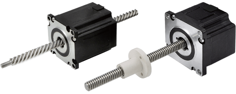
How do external linear (traveling-nut) actuators operate?
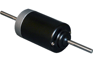
A traveling-screw linear actuator has a lead screw that passes entirely through the motor. In a traveling-screw linear actuator, the motor "crawls" up and down a lead screw that is restrained from rotating. The only rotating parts are inside the motor. In some designs, the rotating parts may not even be visible from the outside of the screw actuator.
Non-captive (traveling-screw) linear actuator operation
Some lead screws have multiple "starts." This means that they have multiple threads alternating on the same shaft. One simple way to visualize the multiple starts lead screw is the multiple color stripes on a candy cane. Multiple starts lead screws provide for more adjustment capability between thread pitch and the nut/screw thread contact area, which will determine the extension speed and load carrying capacity (of the threads), respectively.

The multiple color stripes on the candy resemble a lead screw with multiple starts
Static Load Capacity of Linear Actuators
Screw-type linear actuators can have a static load capacity, meaning that when the motor stops, the actuator is essentially locked in place and can support the load that is either pulling or pushing on the actuator. The braking force of the linear actuator varies with the angular pitch of the screw threads and the specific design of the threads.
Acme screws have a very high static load capacity, while ball screws have an extremely low load capacity and are nearly free-floating. Generally speaking, it is not possible to vary the static load capacity of screw-type linear actuators without additional technology. The screw thread pitch and drive nut design of the screw actuator defines the specific load capacity that cannot be dynamically adjusted.
Dynamic Load Capacity of Linear Actuators
A dynamic load capacity is in some designs added to a screw-type linear actuator using an electromagnetic brake system, which applies friction to the rotating drive nut. For example, a spring may be used to apply brake pads to the drive nut, holding it in position when power is turned off. When the actuator needs to be moved, an electromagnet counteracts the spring and releases the braking force on the drive nut. Similarly, an electromagnetic ratchet mechanism can be used with a screw-type linear actuator so that the drive system lifting a load will lock in position when power to the actuator is turned off. To lower the actuator, an electromagnet is used to counteract the spring force and unlock the ratchet.
Types of Linear Actuators
Mechanical Linear Actuators
Mechanical linear actuators typically operate by the conversion of rotary motion into linear motion (motion in a straight line). Mechanical linear actuators convert rotary motion of a control knob or handle into linear displacement using screws and/or gears to which the knob or handle is attached. A jackscrew or car jack is a familiar mechanical linear actuator.
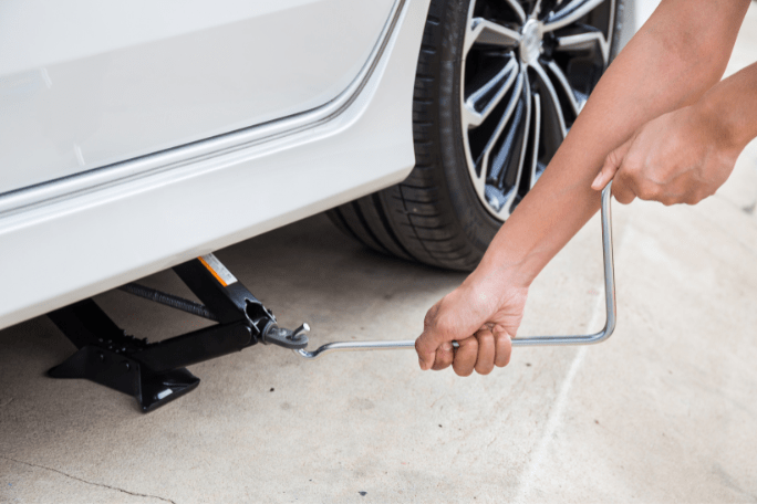
A car jack is a simple example of a mechanical actuator
Another type of linear actuator is based on the segmented spindle. Rotation of the jack handle is converted mechanically into the linear motion of the jack head. Mechanical linear actuators are also frequently used in the field of lasers and optics to manipulate the position of linear stages, rotary stages, mirror mounts, goniometers and other positioning instruments. For accurate and repeatable positioning, index marks may be used on control knobs. Some linear actuator designs include an encoder and digital position readout. These are similar to the adjustment knobs used on micrometers, except that their purpose is position adjustment rather than position measurement. Conversion is typically made using a few simple mechanisms:
- Screws: lead screw, screw jack, ball screw and roller screw linear actuators all operate on the principles and functions of a simple screw. By rotating the actuator's nut, the screw shaft moves in a straight line.
- Wheel and Axle: Hoist, winch, rack and pinion, chain drive, belt drive, rigid chain and rigid belt linear actuators operate on the principles and functions of the wheel and axle, wherein a rotating wheel moves a cable, rack, chain or belt to produce linear motion.
- Cam: Cam linear actuators function on a principle similar to that of the wedge, but provide relatively limited travel. As a wheel-like cam rotates, its eccentric shape provides thrust at the base of a shaft.
Some mechanical linear actuators only pull (such as hoists, chain drive and belt drives), while other types only push (such as a cam actuator). Pneumatic and hydraulic cylinders, or lead screw linear actuators can be designed to provide force in both directions. The selection of the linear actuator is dependent upon the application and budget.
Hydraulic Linear Actuators
Hydraulic linear actuators, sometimes referred to as or hydraulic cylinders, typically involve a hollow cylinder with a piston inserted into it. An unbalanced pressure applied to the piston provides the necessary force that moves an external object. Since liquids are nearly incompressible, a hydraulic cylinder can provide controlled precise linear displacement of the piston. The displacement is only along the axis of the piston. Although the term "hydraulic actuator" refers to a device controlled by a hydraulic pump, an example of a manually operated hydraulic linear actuator is a simple hydraulic car jack.
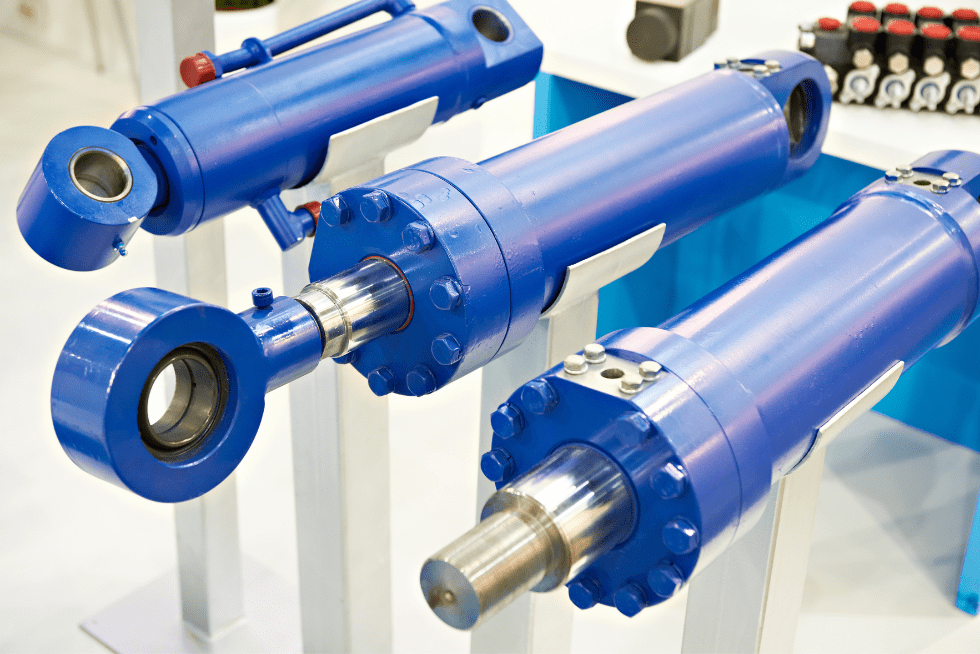
Hydraulic cylinders
Pneumatic Linear Actuators
Pneumatic linear actuators, sometimes referred to as pneumatic cylinders, are similar to hydraulic linear actuators except they use compressed gas to provide pressure, rather than a liquid force.
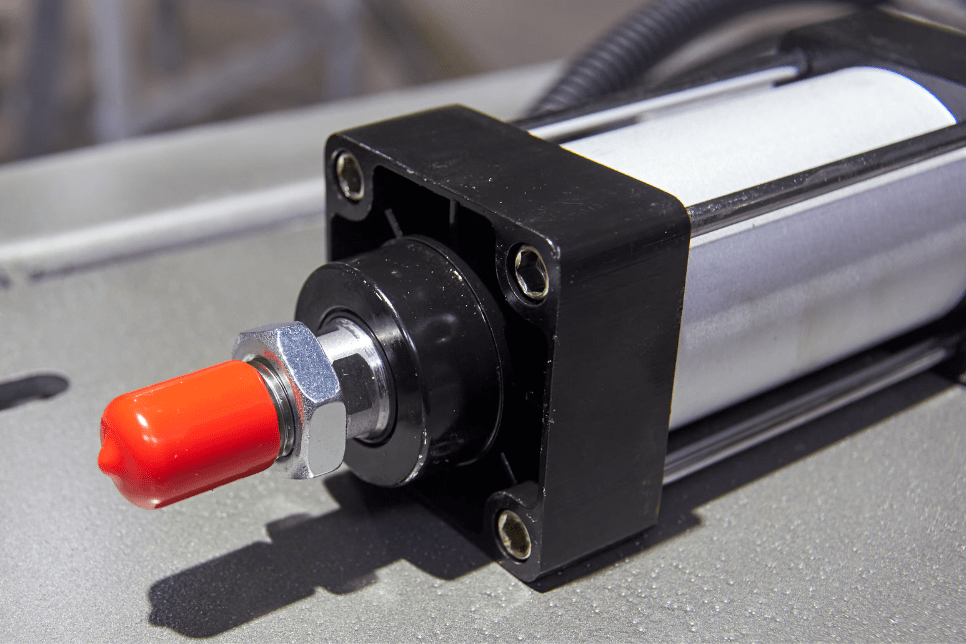
Pneumatic cylinder
Piezoelectric Linear Actuators
The piezoelectric effect is a property of certain materials in which the application of a voltage to the material causes it to expand. Very high voltages correspond to only tiny expansions. As a result, piezoelectric linear actuators can achieve extremely fine positioning resolution. The downside to the piezoelectric linear actuator is that it has a very short range of motion. In addition, piezoelectric materials exhibit hysteresis, which makes it difficult to control its expansion in a repeatable manner.
Electromechanical Linear Actuators
Electromechanical linear actuators are similar to mechanical actuators, the only difference being that the control knob or handle is replaced with an electric motor. Rotary motion of the motor is converted into linear displacement of the actuator. There are many designs of modern linear actuators. Every linear actuator manufacturer has their own proprietary methods and designs, making it difficult to cross parts from one manufacturer to another for a given application.
The following is a example description of a very simple electromechanical linear actuator. Typically, an electric motor is mechanically connected to rotate a lead screw. A lead screw has a continuous helical thread machined on its circumference running along the length (similar to the thread on a bolt). Threaded onto the lead screw is a lead nut or ball nut with corresponding helical threads. The nut is prevented from rotating with the lead screw (typically the nut interlocks with a non-rotating part of the actuator body). Therefore, when the lead screw is rotated, the nut is driven along the threads. The direction of motion of the nut will depend on the direction of rotation of the lead screw. By connecting to the nut, the motion can be converted to usable linear displacement.
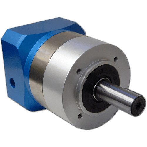
Standard Construction or Compact Construction?
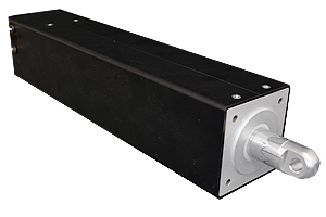
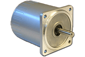
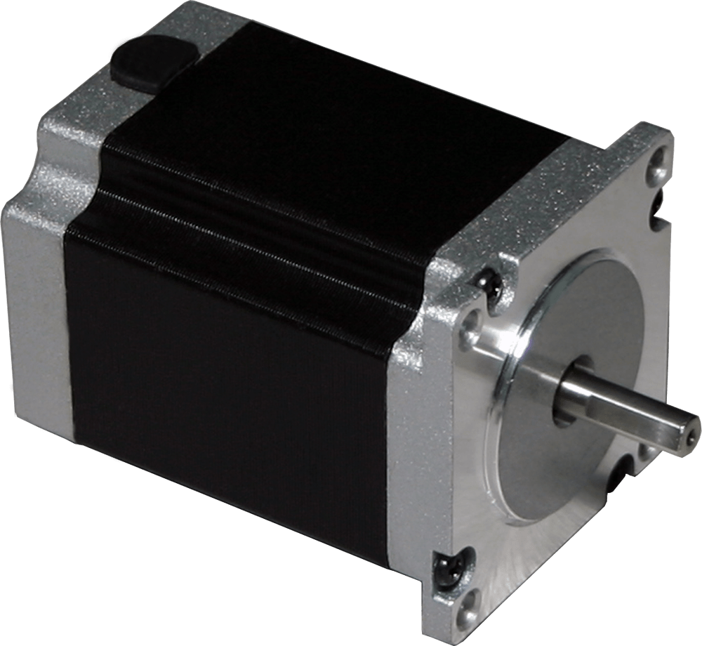
A linear actuator using standard motors will typically use the motor as a separate cylinder attached to the side of the actuator, either parallel with the actuator or stuck out to the side, positioned perpendicular to the actuator. Sometimes the motor is attached to the back end of the actuator. The drive motor is of typical construction with a solid drive shaft that is geared to the drive nut or drive screw of the linear actuator.
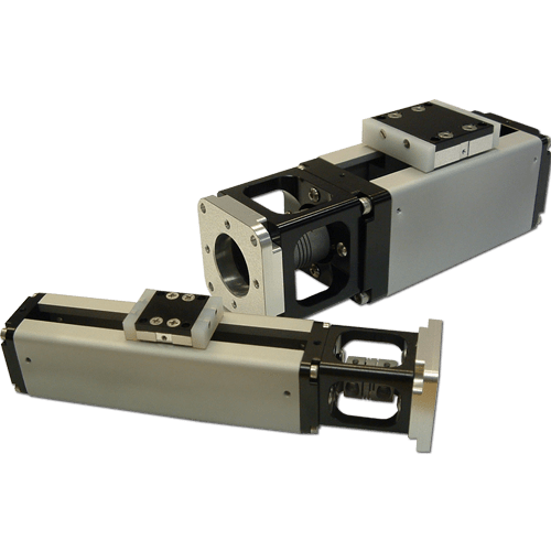
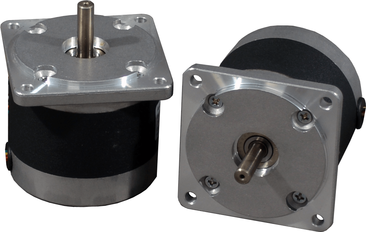
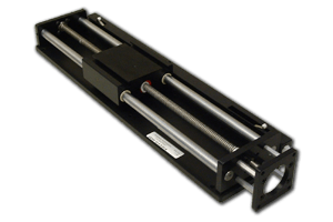
Compact linear actuators may only be about 6 inches long, motor included
Compact linear actuators use specially designed motors that fit the motor and actuator components into the smallest possible footprint. In such cases, the inner diameter of the motor shaft can be enlarged, so that the drive shaft can be hollow. The drive screw and nut can therefore occupy the center of the motor, with no need for additional gearing between the motor and the drive screw. Similarly, the motor can be made to have a small outer diameter, with the pole faces stretched out lengthwise so that the motor will provide high torque while fitting in a small diameter design.
Motor-Type Linear Actuators
A motor-type linear actuator basically functions the same as a rotary electric motor with the rotor and stator circular magnetic field components designed so that they are laid out in a straight line. Whereas a rotary motor rotates and re-uses the same magnetic pole faces again and again, the magnetic field structures of a motor-type linear actuator are physically repeated across the length of the actuator. Since the motor moves in a linear fashion to begin with, no lead screw is needed to convert rotary motion to linear. While high capacity is possible, the material and/or motor limitations on most designs are surpassed relatively quickly due to a reliance solely on magnetic attraction and repulsion forces. Most linear actuator motors have a low load capacity compared to other types of linear actuators. However, linear actuator motors have an advantage in outdoor or dirty environments in that the two halves do not need to contact each other, so the electromagnetic drive coils can be waterproofed and sealed against moisture and corrosion. The linear actuator motor design provides for a very long service life, so it can be an economical choice for some applications.
Special Design: Telescoping Linear Actuator
Telescoping linear actuators are specialized linear actuators that are typically used where space restrictions or other requirements dictate the best fit. The telescoping linear actuator's range of motion is many times greater than the unextended length of the actuating member. A common form is made of concentric tubes of approximately equal length that extend and retract like sleeves, one inside the other, such as the telescopic cylinder. Other more specialized telescoping linear actuators use actuating members that act as rigid linear shafts when extended, but break that line by folding, separating into pieces and/or uncoiling when retracted.
Examples of telescoping linear actuators include:
- Helical Band Linear Actuators
- Rigid Belt Linear Actuators
- Rigid Chain Linear Actuators
- Segmented Spindle Linear Actuators
Anaheim Automation Carries the Following Types of Linear Actuators
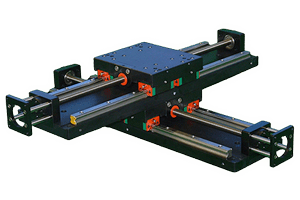
Screw-Driven Linear Actuators
Also called linear stages or linear actuator tables, screw-driven linear actuators are suitable for low-speeds, heavy loads, and high-inertial loads. These devices are typically used in positioning equipment, CNC machines, and anywhere else slow point-to-point movement is required.
Belt-Driven Actuators
Designed for high-speeds and light loads, belt-driven actuators are only suitable for low-inertial loads. Common applications for belt actuators include automated windows and doors, high-speed data acquisition, and scanning devices.
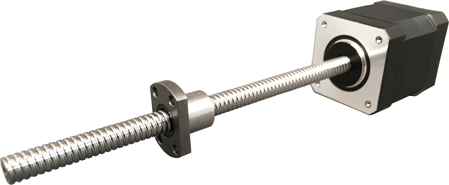
Rod-Style Actuators
Rod actuators excel at lifting and thrusting applications, with thrust-bearings built into the actuators themselves. They are similar to screw-driven tables in terms of speed, load, positioning, and accuracy capabilities. Rod actuators offer a compact, collapsible design great for projects where space constraints are a concern.
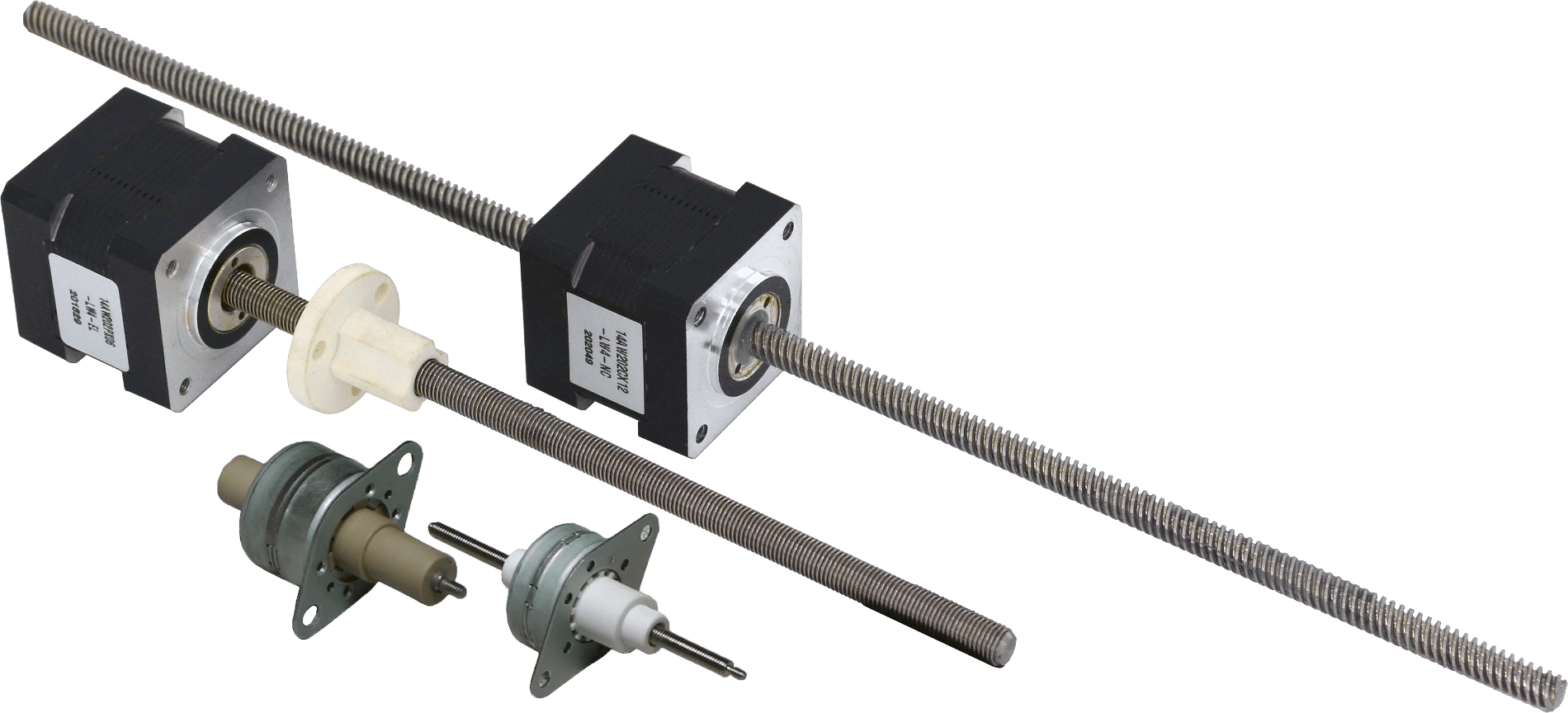
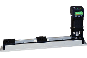
Stepper Motor Linear Actuators
Stepper linear actuators are intended for point-to-point positioning applications. This type of actuator is best suited for applications with light loads and slow speeds. Steppers are open loop accurate, so they do not require an encoder for accurate positioning.
BLDC Motors with Integrated Ball Screws
Our brushless DC linear actuators are great for high-speed motion. Their specialty is delivering power density at high speeds, rather than the high accuracy of a stepper. Brushless linear actuators may require an encoder to obtain accurate positioning data.
Advantages and Disadvantages of Specific Linear Actuator Designs
Advantages of Linear Actuators
Each type of linear actuator is made differently and has its own advantages. Mechanical linear actuators, for example, are relatively inexpensive, reusable, and self-contained. Piezoelectric linear actuators can create extremely small linear motions and can consequently be used for microcomputer and micro-mechanical applications. Hydraulic linear actuators can produce a large amount of pressure, and therefore, can be used for heavy duty applications. Pneumatic linear actuators are powerful, compact, lightweight, very simply designed, and provide repeatable motion. See chart for comparisons of linear actuator types.
Disadvantages of Linear Actuators
While each linear actuator has its own advantages, each also has its disadvantages. For example, mechanical linear actuators are strictly manual and cannot be automated. Piezoelectric linear actuators are slow, can only move across small areas, are very expensive, require a high voltage to be effective, and require a secondary force to push the shaft back into its initial position. See chart for comparisons of linear actuator types.
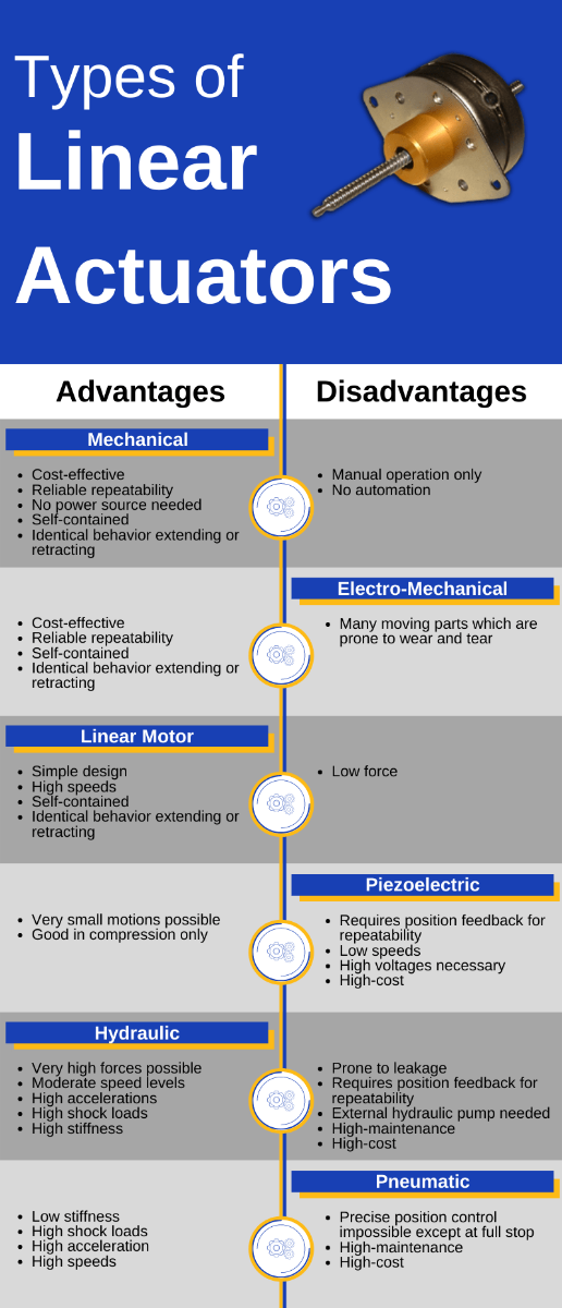
Comparison of the advantages and disadvantages of various types of linear actuators
How to Select a Linear Actuator for an Application:
"Linear actuator" is a broad term covering many different types of devices. The process of selecting the best device for a specific application is dependent upon the user's diligent research and development practices. It is difficult to compare the specifications between linear actuator manufacturers, as there is very little standardization within the industry. Each type of linear actuator fulfills a different set of design requirements.
There are many different types of motors that can be used in a linear actuator system as well. These include DC Brush, DC Brushless, Servo, Stepper, and in some cases, even AC induction motors. The application requirements and the loads the actuator is designed to move will dictate the best motor option. For example, a linear actuator using an integral horsepower AC induction motor driving a lead screw can be used to actuate a large valve in a refinery. In this case, extreme accuracy and high resolution (down to a thousandth of an inch) would not be required, but high force and speed are critical to the application.
For electromechanical linear actuators used in laboratory instrumentation, robotics, optical and laser equipment, or X-Y tables, fine resolution (measured in microns) and high accuracy may require the use of a fractional horsepower stepper motor linear actuator with a fine pitch lead screw. Because there are many variations in the electromechanical linear actuator system, it is critical to understand all design requirements and application constraints for the proper selection.
The following is a guideline to the selection of the linear actuator, and will assist you through the process step by step. Carefully consider each step and you will be able to narrow down your choice.
BEFORE YOU START
Important notes: Linear actuators are used in a variety of applications across numerous industries, including medical equipment, agriculture machinery, high-voltage switch gears, train and bus doors, and factory processes and assembly machinery. Typical use cases include medical beds, patient lifters, wheelchairs, adjustable tables and workstations, diagnostics, to name a few. Each linear actuator application has unique requirements.
Manufacturers throughout the world offer innumerable models of linear actuators in a wide variety of stroke sizes, speeds, voltage and types. With the availability of so many manufacturers, models and options, selecting the right linear actuator for your application can be a daunting task. When contacting a manufacturer for application assistance for a linear actuator, please be prepared to provide as many of the application requirements as possible, including the environment in which you plan to use the linear actuator. Most linear actuators are built either for high speed, high force, or a compromise between the two.
Starting the Process
Step One: The Basics
Describe and discuss the application in as much detail as possible with a knowledgeable and experienced supplier. At this stage, focus on basic specifications for load, actuator, and power and control. When considering a linear actuator for a specific application, the most important specifications are: travel distance, speed, force, accuracy and lifetime requirements. Other aspects of the linear actuator application will help determine which products to choose. The following questions must be answered before the selection process can start:
- What type of energy source will you use? Air, fluid, electricity? Answering this question will eliminate many manufacturers and linear actuator types.
- Determine the amount of force required. This may be the weight of an object you are lifting or friction that needs to be overcome. How much force (in newtons or pounds-force) and in what directions (push, pull, vertical, and/or horizontal) will the actuator need to move? (Force is a function of maximum and average dynamic loads.) Rule out any linear actuators that are not capable of producing enough force.
- Speed: How fast (millimeters/second or inches/second) will the actuator need to move? Decide how fast you need to move; you can rule out any linear actuators that are too fast or too slow. Determining the speed combined with the force from step one will give you the mechanical power required.
- Distance: Define how far your actuator needs to travel, also known as the stroke length. Whenever possible, select the standard catalog options. How far will the actuator need to move? This will factor in both the stroke and retracted lengths and is usually expressed in millimeters. Special requirements are generally more costly. Important: Keep in mind that the longer the stroke, the longer the linear actuator will be when fully retracted. This is especially important if you need to fit into an existing space.
- Duty Cycle: How often will the actuator operate, and how much time will elapse between operations? (This refers to the "duty cycle," which will be based on the number of expected repetitions per unit of time in hours/day, minutes/hour, and/or strokes/minute.) Check the duty cycle rating of your remaining choices. Except for high-end servo units, most linear actuators may not operate continuously without overheating.
- Options to consider: What are the power supply options (motor vs. battery)? A battery-powered application will probably require a DC motor rated the same as the battery voltage. However, an AC powered application does not necessarily need an AC motor because AC is fairly easily converted to any DC voltage. Be flexible when choosing options such as built-in limit switches and position feedback devices such as potentiometers and encoders. Consider that limit switches, for example, can often be incorporated into part of your mechanism rather than being part of the actuator itself.
- Environmental Considerations: Will environmental factors (temperature variations, moisture, vibration, or end-product shock) pose a challenge to operation? Most linear actuators can operate well in an indoor environment, but harsh outdoor conditions, extreme temperatures or submersion will drastically limit your product choices. Sometimes it is easier to provide some external protection to the unit rather than find one with the proper ingress protection rating that meets all your other requirements.
Narrowing Down the Selection of the Linear Actuator
Careful review of your linear actuator application can help to eliminate costly mistakes and provide for optimal system performance.
Step Two: Beyond the Basics – Options to Consider
When a system is tailored for an application, the specific requirements will influence both the design and the manufacturing processes. Regardless of end use, an actuation system is designed by first identifying basic needs, and then evaluating certain key parameters that ultimately affect the overall system operation.
Electromechanical linear actuators are designed to provide precision, efficiency, accuracy, and repeatability in effecting and controlling linear movement. These devices serve as practical, efficient, and relatively maintenance-free alternatives to their hydraulic or pneumatic actuator counterparts. Depending on type and manufacturer, today's electromechanical linear actuators can handle loads of up to 3,000 pounds (13 kilonewtons) and deliver speeds of up to 6 inches/second (150 millimeters/second), with strokes ranging from 2 inches (50 millimeters) to 60 inches (1,500 millimeters). Actuators can be self-contained in aluminum, zinc, or polymer housings and ready to mount for easy plug-in operation (using either AC or DC power supplies).
What's more, actuators featuring both modular design and open architecture enable interchangeable internal and external components, according to specifications. Please note that standard components, including the types of drive screws, motors, front and rear attachments, controls, and limit switches used, will allow for desired customization without the costs typically associated with special modifications.
Note: The specific parameters that play a crucial role in every electromechanical actuator application are the: electrical power in, duty cycle, and actuator efficiency. Answering the following questions will help you to define the linear actuator further:
- What is the desired lifetime for the end product? (Those answers will impact virtually every component within a linear actuator system.)
- How will the actuator be mounted? Will front and/or back mounts require special configurations?
- Does the application suggest particular safety mechanisms (e.g., "manual operators" for use in case of emergency)?
- Is space limited? (If so, the actuator will have to be designed to fit in a specific footprint.)
- If a motor is utilized, what is its type (AC, DC, or special) and voltage?
- Is feedback required for speed and/or position? (This will indicate a need for add-on components, such as encoders.)
Step Three: The Power Factor
A linear actuator is a device that produces linear motion by utilizing some external energy source. As far as the source of energy used is concerned, it can be piezoelectric, pneumatic, hydraulic, mechanical, electro-mechanical, etc. A linear actuator system draws principles from both electrical and mechanical engineering disciplines. Consequently, power (defined in Watts) is usually the first requirement to be calculated. In order to get mechanical power out of an electric linear actuator, it is necessary to put electrical power into the system. Mechanical power out is usually the easier of the two to define because all that is needed for its calculation is the force, or the load that will be moved, and the speed required.
If the parameters are in metric (SI) units, multiply the force (in Newtons) by the speed (in millimeters/second) to obtain Watts. (To convert pounds to Newtons, multiply by 4.448; to convert inches to millimeters, multiply by 25.4.)
Mechanical power out (P0):
P0 = F x v
F = Force (N)
v = Velocity (meters/sec)
Information regarding electrical power can be ascertained through performance graphs and charts from suppliers' specification sheets. Suppliers chart this information differently, but more often than not, there are graphs for force vs. speed and force vs. current draw at a specified voltage. This data is often presented in two graphs or combined in one. The current draw may also be presented in tabular form. In addition, factors will be given based on a duty-cycle curve. The relevant formula is as follows:
Electrical power in (Pi):
Pi = E x I
E = Voltage (V)
I = Current (A)
Step Four: Calculating Duty Cycle
Users will want to establish the duty-cycle factor (sometimes called the "derating factor"). Duty cycle is important. Sometimes the preliminary actuator selection may not meet all of an application's operating requirements. The duty cycle indicates both how often an actuator will operate and how much time there is between operations. Because the power lost to inefficiency dissipates as heat, the actuator component with the lowest allowable temperature (usually this is the motor) establishes the duty-cycle limit for the complete linear actuator system. Please note: There are some heat losses from friction in a gearbox, and via ball-screw and acme-screw drive systems.
To demonstrate how the duty cycle is calculated, assume an actuator runs for 10 seconds cumulative, up and down, and then doesn't run for another 40 seconds. The duty cycle is 10/(40+10), or 20%. If duty cycle is increased, either load or speed must be reduced. Conversely, if either load or speed decreases, duty cycle can increase. The duty cycle is relatively easy to determine if a linear actuator is used on a machine or production device. In other, less predictable applications or those where the linear actuator will be used infrequently, it is advisable to estimate the worst-case scenario in order to assign a meaningful duty-cycle calculation. It is not advisable to operate on the edge of the manufacturer's power curves because this might cause the linear actuator and other components to run too hot. However, in some applications where the duty cycle is 10% or less, the actuator can run to the limit of its power curves.
Step Five: Ascertaining 'Efficiency' and Expected Life
A system's "efficiency" is usually missing from most manufacturers' literature, but it can tell the user how hot the actuator may get during operation, whether holding brakes should be specified in the system if the actuator uses a ball screw, and how long batteries may last in battery-powered systems, among other pertinent data. Calculating efficiency from performance curves is simple: divide mechanical power out by electrical power in. This yields the efficiency percentage.
While these factors are being calculated and decision making is moving toward final selection, one additional parameter should be addressed: the application's expected lifetime. Although linear actuator components (e.g., the motor or screw) can be replaced, most actuators cannot be easily repaired. In addition, it is important to cover application life expectancy because suppliers will sometimes indicate acme or ball screw life at a certain load, or include mathematical formulae to calculate life based on application parameters. A good design practice is to strive to have the screw and motor life expectancies match as closely as possible.
In those cases where an existing linear actuator must be replaced, ensure that the application engineer has all the necessary information to ensure a good fit. Whenever a linear actuator is subject to replacement, it is recommended to review the application as if it were new.
Other Selection Considerations: Budget and Experience
Having a clear picture of a linear actuator system budget in your mind will help in selecting the best product at an affordable price. Advanced budget planning can definitely save the user a lot of time in the selection process by eliminating some types that are too expensive for the application. As mentioned earlier, there are many companies providing linear actuators to the customers based on their requirements. It is important to choose a reliable company for the best results in terms of the actuator features and price.
Common products associated with motion control systems using linear actuators:
AC Motor: An AC Motor is an electric motor that is driven by alternating current. The AC Motor is used in the conversion of electrical energy into mechanical energy. This mechanical energy is made from utilizing the force that is exerted by the rotating magnetic fields produced by the alternating current that flows through its coils. The AC Motor is made up of two major components: the stationary stator that is on the outside and has coils supplied with AC current, and the inside rotor that is attached to the output shaft. Anaheim Automation has a full line of AC motors with many options for budget considerations. To select the best fit for your application, refer to Anaheim Automation's AC Motors.
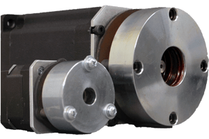
Brake: A brake is a device that resists and reduces the motion of a mechanism. When the brake is engaged, it "slips" until the driving mechanism stops. When the brake is disengaged, the mechanism can rotate freely. Brakes are similar in principle to clutches. A clutch couples two mechanisms in order to transmit motion and power, while a brake "couples" a mechanism to a fixed frame in order to reduce motion and power. Anaheim Automation offers a line of friction brakes in four series, in NEMA sizes 23, 34 and 42. Perfect for stopping and holding applications, these compact brakes can handle high torque requirements, from 80 to 1,152 oz-in. Their low-voltage design provides for applications that are susceptible to weak battery, brown out, or long wiring runs. To select the best fit for your application, refer to the Anaheim Automation's Accessories/Brakes.
Brush DC Motor: A brush DC motor is a direct current (DC) motor that utilizes a relatively simple design. The brush motor is an electric motor that uses electricity and a magnetic field to produce torque, which rotates the motor. At its most simple design, a brush motor requires two magnets of opposite polarity and an electric coil, which acts as an electromagnet. The repellent and attractive electromagnetic forces of the magnets provide the torque that causes the brush motor to rotate. Anaheim Automation has a full line of brush DC motors with many options for budget considerations. To select the best fit for your application, refer to Anaheim Automation's Brush Motors.
Brushless DC Motor (BLDC): A brushless DC motor is an electric motor powered by direct current (DC). Though typically more expensive than the standard electric or brushed motor, the brushless DC has considerable advantages over its predecessor. Most notably, a brushless DC motor boasts better performance and suffers less wear than brushed motors of similar size. Anaheim Automation has a full line of brushless DC motors with many options for budget considerations. To select the best fit for your application, refer to Anaheim Automation's Brushless Motors.
Clutch: A clutch is a device that transmits power between two mechanisms (usually rotating) selectively. When the clutch is engaged, it "slips" until the two mechanisms rotate at the same speed and power is transmitted. When the clutch is disengaged, the two mechanisms are de-coupled and allowed to rotate at different speeds. Power is not transmitted. Clutches are similar in principle to brakes. In a brake, the driven mechanism would be connected to a fixed frame.
Torque Limiter (Torq/Gard and Centric Clutches) Uses: Centric Overload Clutches and Torq/Gard Clutches provide machine protection and reduced repair time during jamming load conditions. Mechanical or pneumatic torque limiters provide consistent torque levels after many overloads. Unlike friction style or shear pin-type torque limiters, Centric Overload Clutches and Torq/Gard can provide an accurate method of resetting the torque with no operator intervention. A single position clutch will re-engage in the exact rotational position each time. This is often necessary for a system wherein timing is critical, such as bottling, packaging, and paper converting type applications.
Coupling: A coupling is a device that connects two generally coaxial (inline) shafts at their ends in order to transmit power between them. A coupling can be incorporated with a clutch to serve as a clutch-coupling or a torque limiter. At high speeds, couplings are capable of transmitting high torque at a constant velocity. Certain types of couplings may be able to compensate for lateral, axial, and angular misalignments.
Gearbox: A gearbox is a mechanical device that transfers energy from one device to another. A gearbox is used to increase torque while reducing speed. Torque is the power generated through the bending or twisting of a solid material. This term is often used interchangeably with transmission. Anaheim Automation has a full line of gearboxes with many options for budget consideration. To select the best fit for your application, refer to Anaheim Automation's Gearboxes.
Linear Actuator Motors: Linear actuator motors are motors that provide push and pull motive force in a straight line. There are many uses for many different types of linear actuator motors: some will be used to move work tables on industrial machines, while others are better suited to modulate control valves, drive material handling equipment, bottling and packaging and robotics, and move printer and scanner heads back and forth on equipment. Large linear actuator motors can drive shovels and lifts on construction equipment. They can be used for home automation projects, such as providing the oscillatory motion of audio loudspeakers, lowering or raising televisions, and in some solar energy systems. Anaheim Automation offers both Stepper Motor Linear Actuators as well as BLDC Linear Actuators with Ball Screws.
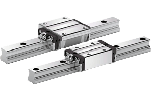
Linear Guide: A linear guide is a mechanical linear motion bearing system or linear slide that is designed to provide free motion. Linear guides are sometimes referred to as linear actuators. Anaheim Automation has a full line of linear guides that are precision rails and matched bearing blocks, in many sizes (including miniature) with options for all budgets. To select the best fit for your application, refer to the Anaheim Automation's Linear Guides.
Rotary Union: A rotary union, or rotating union, is a device used to conduct fluids and gases from one point to another, often under high pressure. Additionally, a rotating union is designed to lock onto an input valve while rotating or swiveling to meet an outlet. Many rotary unions incorporate multiple ports, some of which are designed to handle different types of material simultaneously.
Slip Ring: A slip ring (in electrical engineering terms) is a method of making an electrical connection through a rotating assembly. Slip rings, also called rotary electrical interfaces, rotating electrical connectors, collectors, swivels, or electrical rotary joints, are commonly found in electrical generators for AC systems and alternators and in packaging machinery, cable reels, and wind turbines. One of the two rings is connected to one end of the armature winding and the other is connected to the other end of the armature winding.
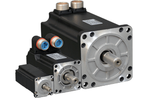
Servo Motor: A servo motor is defined as an automatic device that uses an error-correction routine to correct its motion. The term servo can be applied to systems other than a servo motor: systems that use a feedback mechanism such as an encoder or other feedback device to control the motion parameters. Typically, when the term servo is used, it applies to a 'servo motor' but is also used as a general control term, meaning that a feedback loop is used to position an item. Anaheim Automation has a full line of servo motors, including linear actuator servo motors, with many options for budget considerations. To select the best fit for your application, refer to Anaheim Automation's Linear Servo Actuators.
Stepper Motor: A stepper motor is an electrical device that divides the full rotation of the motor into individual parts called steps. Generally, stepper motors are brushless in order to facilitate a synchronous rotation and operate without the input of an external source on the gear itself. Simply stated, stepper motors are designed with electromagnets which are arranged in specific locations around the shaft, each engraved with teeth. These teeth match the teeth that are placed on the gear itself. As the gear rotates, one section matches with the teeth of the first electromagnet, offsetting the teeth from the other electromagnets, and repeating the action as it rotates. Anaheim Automation has a full line of stepper motors, including linear actuator stepper motors, with many options for budget considerations.
Table/Slide/Stage: The terms table, slide, stage and linear actuator are often used inter-changeably, even though there are significant differences among them. Anaheim Automation carries two types of screw-driven positioning tables: standard screw-driven and precision screw-driven tables. Some linear tables are designed with unsupported rails and others with supported rails that utilize the stainless steel 400 series precision rolled lead screw, accurate up to 0.003"ft, with a burnished finish and a zero backlash nut. These screw-driven tables (acme and ball screw) are available as open-loop or closed-loop systems (wherein stepper motors are assembled with encoders). Available options are: light or heavy-duty configurations, travel lengths, homing and limit switches, and lead screw pitch. Ideal for pick-and-place operations, circular and linear interpolation, point-to-point motion, pin-insertion, inspection and test equipment, engraving, part positioning, and assembly, these tables yield a great cost/performance ratio. To select the best fit for your application, refer to Anaheim Automation's Tables.
Glossary of Terms for Linear Actuator Motion Systems
Absolute Accuracy
The difference between ideal position and real position.Absolute Positioning
Refers to a motion control system employing position feedback devices to maintain a given mechanical location.ACME Screw
The most common type of lead screw found in machine applications. The ACME thread is a particular type of thread. Compared to a ball screw, ACME lead screws have a very high friction and backlash, both of which are undesirable for high-performance applications.AC Motor
A type of electric motor that runs on alternating current. AC motors are more commonly used in industry than DC motors, but do not operate well at low speeds.Accuracy
The relative status of something compared to its absolute or perfect value. In motion control this will most often be a position description. For example, a command may be set to 4.0 inches. The accuracy of the system will be defined on how close to the absolute value of 4.0 inches the system can affect the move. Accuracy may be defined as a one-time incident or the average over a number of cycles or motions. Positioning accuracy will normally be defined in terms of deviation (+/- from the theoretical) or limits (acceptable variation from the theoretical: i.e. 3.8 - 4.3 inches define acceptable limits of variation around a theoretical point.Actual Position
The position of an axis relative to the commanded position. This may be the position at the end of the command move, or the lag between command position at any point during the move and the actual position of the axis at that point. The latter is commonly referred to as following error.ARC Minute
An angular measurement equal to 1/60th of a degree.Axes of Motion:
The specific major directions along which controlled movement occurs. Usually referred to as the number of these major directions employed in a specific machine. Generally defined as follows:- X: Linear motion in a positioning direction
- Y: Linear motion perpendicular to the positioning direction
- Z: Vertical linear movement
- A: Angular motion around X (roll)
- B: Angular motion around Y (pitch)
- C: Angular motion around Z (yaw)
Axial Load
The terms 'axial load' and 'radial load' with respect to the bearing: Axial load is any load that is parallel to the axis of rotation of the bearing. Radial load is any load that is perpendicular to the axis of rotation.Axial Play
The axial displacement of the shaft due to a reversal of an axial force.Axis
A principal direction along which movement of a tool, component, or workpiece occurs. The components that control each degree of freedom in a machine can be considered an axis. An X-Y-Z machine has 3 axes, where the X and Y axes control movement in the horizontal plane and the Z axis controls up and down motion. Each axis can consist of a controller, drive, motor, and transmission components necessary to couple to the load.Backlash
The play caused by loose connections between mechanical components. Backlash becomes a problem when an axis changes direction. When a motor turns, it pushes all the gears together in one direction. When the motor reverses direction the gear teeth separate from one side and meet on the other side. The distance of separation is the backlash.Ball Screw
Ball screws are highly efficient, low-friction and low backlash lead screw devices that use ball bearings rolling in a channel cut into the screw. The low friction and backlash attributes are extremely valuable for precision applications where they are used to drive the axes of the machine.Brushless Motor
Brushless Motors are a class of motors that operate using electronic commutation of phase currents, rather than electromechanical (brush-type) commutation. Brushless motors typically have a permanent magnet rotor and a wound stator.Circular Interpolation
The generation of an apparently circular motion through the coordinated movements of two axes. The actual path is a series of straight line approximations generated by software algorithms.Collision Detection
The use of sensors to detect the imminent impact of two or more parts in a motion control system. The signals from the detection sensors can be used to stop motion or to provide a ramped slow down for a "soft" mating of the approaching components.Coordination
The integration of the movements of two or more axes of motion, so that the resultant motion is the path which none of the axes are capable of independently. Coordination may also involve the use of sensors and other internal or external commands in the integration effort which assist in effecting the movement or work desired.Coupling
Also known as a "coupler." The transfer of energy from one circuit to another by means of the mutual capacitance between them. In feedback and control systems this is considered to be electrical noise and is a common problem.Cut-to-Length
A sub-routine within a motion control process or a standalone process in which feed material is processed at a preset distance. The distance is set prior to the performance of the task, and/or a secondary task such as a cut-off of the feed material. Feedback systems are employed to ensure repeatability of the preset feed length.Detent Torque
Detent torque is the holding torque when no current is flowing in the motor. The maximum torque which can be applied to the shaft of an un-energized step motor without causing continuous rotation. The minimal torque present in an un-energized motor. The detent torque of a step motor is typically about 1% of its static energized torque.Dynamic Torque
The torque developed by a motor while stepping at low rates.Efficiency
In physics: the efficient energy use, useful work per quantity of energy, or mechanical advantage over ideal mechanical advantage, often denoted by the Greek lowercase letter η (Eta). In thermodynamics: efficiency is energy conversion efficiency, a measure of second law thermodynamic loss. Thermal efficiency: useful work per the higher heating value of the fuel. In computing: Algorithmic efficiency is optimizing the speed and memory requirements of a computer program, while storage efficiency as the effectiveness of computer data storage.Electronic Clutch
The process of generating a slave profile based on master position or time periods by enabling and disabling electronic cam or gearing functions.Electronic Gearing
A method that stimulates mechanical gears by electrically synchronizing one closed-loop axis to a second axis (open- or closed-loop) through a variable ratio.Electronic Line Shaft
A virtual axis that is used as the master axis on a machine to which other axes are synchronized by electronic gearing or camming profiles.Encoder
An encoder is a feedback device. It consists of a disc, vane, or reflector, typically attached to a motor shaft to provide digital pulses, which are provided to a translator and /or counters. This provides positional information if fed into a counter. Speed information may be derived if the time between successive pulses is measured and decoded.Encoder Resolution
The number of electrically identified positions occurring in 360 degrees of input shaft rotation.Event
A change-of-state of an input parameter, such as the triggering of a limit switch or proximity sensor.Fault
The error received when a drive or control has attempted an illegal process and becomes disabled.Feedback
Feedback is the measurement of the parameter that is being controlled. For a positioning system to accurately compensate for an error, the actual position must be known relative to the commanded position. In this case, position feedback would be used to provide the actual position.Feedback Signal
The actual value detected by a sensor as a process is taking place. The feedback signal is part of a closed-loop control system.Feedforward
A method that "precompensates" a control loop for known errors due to motor, drive, or load characteristics to improve response. It depends only on the command, not the measured error.Gantry
An overhead framework that is designed to linearly move in the X, Y, and/or Z axes. Tooling or other devices are generally designed into the framework to perform various functions as it moves from one location to another.Gearbox
A system of gears that transmits mechanical power from a prime mover, such as an electric motor, to a typically rotary output device at a lower momentum, but a higher torque.Holding Torque
The maximum torque that can be externally applied to the motor shaft without causing continuous rotation when one or more phases of the motor are energized.Home Position
A reference position for all absolute positioning movements. Usually defined by a home limit switch and/or encoder marker. Normally set at power-up.Homing
Locating a unique reference position at power-up for axis calibration.Indexer
In the context of stepper motor-based systems, the indexer is a device that provides step and direction control signals to a stepper motor driver. More sophisticated dedicated stepper motor controllers will also have I/O points and various other higher level functions and programmability similar to a PLC. In many cases, a PLC may be used as an Indexer.Indexing
An axis or axes in the process of moving to a pre-programmed position, at a defined velocity and acceleration/deceleration rate.Interpolation
A coordinated move of two or more axes in a linear and/or circular motion.Jog
An axis running at a fixed velocity and acceleration/deceleration rate, in a selected direction, with no specific destination.Lead
The linear distance a nut on a lead screw travels during one revolution of the lead screw, e.g. in/rev.Lead Screw
A device which converts rotary motion into linear motion.Limits
Sensors within a motion system that alert the control electronics that a physical end of travel has approached and that the motion is not allowed in a specific direction.Linear Actuator
A linear actuator is an actuator that creates motion in a straight line, as contrasted with the rotary motion of a conventional electric motor. Linear actuators are used in machine tools and industrial machinery, in computer peripherals such as disk drives and printers, in valves and dampers, and in many other places where linear motion is required. Hydraulic or pneumatic cylinders inherently produce linear motion; many other mechanisms are used to provide a linear motion from a rotating motor.Linear Servo Motor
A linear servo motor is a "flattened" servo motor where the rotor is on the inside, and the coils are on the outside of a moveable u-channel.Linear Slide
Linear slides are precision products designed to turn motion or torque into straight-line movements. Linear slides are designed to move mounted mechanisms across a given axis. Complete slides normally consist of at least a base, a saddle, adjusting screw and a straight gib.Load
Any external resistance (static or dynamic) to motion that is applied to the motor.On-Axis Accuracy
The difference between ideal position and real position after the compensation of linear errors. Linear errors include: cosine errors, inaccuracy of screw or linear scale pitch, angular deviation at the measuring point (Abbe error) and thermal expansion effects. The relation between absolute accuracy and on-axis accuracy is as follows:Absolute Accuracy = On-Axis Accuracy + Correction Factor x Travel