We use cookies to make your experience better. To comply with the new e-Privacy directive, we need to ask for your consent to set the cookies. Learn more.

BLDC System Design and Selection Guide
Aug 2026 Nicole Jones
Brushless DC (BLDC) motors are widely used in industrial automation, robotics, medical equipment, instrumentation, and other applications across a variety of industries where quiet, efficient, and reliable motion is required. But the BLDC motor is only one factor to consider when designing a complete motion control system. The brushless motor, driver/controller, feedback device, power supply, and mechanical load must all be taken into account to achieve your desired performance.
This guide provides a high-level overview of the key considerations when selecting and integrating a BLDC motor and controller into your system.
What Is a BLDC Motor?
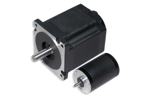
Unlike their Brushed DC counterparts which use mechanical brushes and a commutator, a Brushless DC motor uses electronic commutation. Permanent magnets on the rotor of the BLDC motor interact with electromagnetic fields generated by the stator windings to produce rotation. Because BLDC motors eliminate brushes and brush wear, they can provide:
|
|
A BLDC motor does, however, require an electronic driver or controller to properly energize its wingings.
For a deeper explaination of BLDC motor construction, operation, specs and terminology, see our BLDC Motor Guide.
What Is a BLDC Driver/Controller?
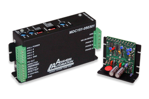
A BLDC driver/controller provides the electronic control necessary to operate the BLDC motor. It manages the current supplied to the motor phases and determines when those phases should be energized. Depending on the controller, functionality may include:
|
|
The controller should be selected together with the motor rather than treated as a separate component.
Learn more about controller operation, control methods, feedback, and specifications in our BLDC Driver/Controller Guide.
Designing a Complete BLDC System
When selecting components for your BLDC system, consider the following relationship:
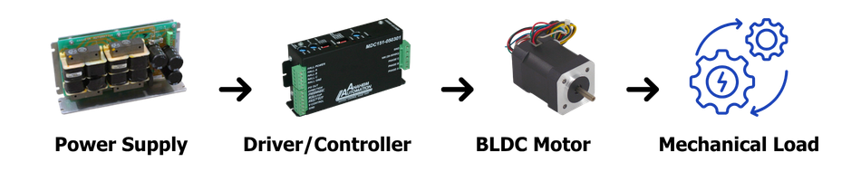
Feedback may be incorporated between the motor and controller for applications requiring closed-loop speed or position control. Additional components may include:
|
Considering these components early on in the design process can help OEMs avoid integration problems later in development.
Top 6 Considerations for BLDC Motor Selection
Brushless motors should be selected based on the following requirements for your application:
Determine the continuous and peak torque required for your system. Consider acceleration, deceleration, startup conditions, and changing loads - not just the application's normal running torque.
Identify both the normal operating speed and maximum required speed. Evaluate the motor's torque-speed curve to make sure adequate torque is available throughout the operating range.
The motor's electrical characteristics must be compatible with the selected controller and available power supply. The controller must also be capable of providing the motor's required continuous and peak current.
Determine whether the application requires:
- Hall sensor feedback
- Sensorless operation
- Encoder feedback
Hall sensors are commonly used for rotor-position detection, while encoders can provide additional speed, direction, or position feedback.
Verify the following requirements:
|
|
For OEM equipment, mechanical compatibility should be evaluated early to minimize redesigns.
When sourcing components, make sure to consider the environmental conditions in which your system will be operating.
|
|
The motor and controller should both be capable of operating reliably under the actual environmental conditions.
Top 6 Considerations for BLDC Controller Selection
Once the motor requirements are established, select a controller that can provide the necessary electrical and control performance.
Verify that the controller's input-voltage range is compatible with the available power supply.
The controller must support the motor's continuous operating current as well as any required peak current during acceleration or transient loads.
Verify compatibility with the following motor specs:
|
|
Depending on the controller, speed or torque commands may be provided through interfaces such as analog voltage, PWM, potentiometers, or digital control signals. Select an interface compatible with the machines PLC, motion controller, or other control architecture.
Determine whether the application requires open-loop or closed-loop operation and whether the controller supports the required feedback device. Closed-loop control may be most beneficial when the application requires improved speed regulation, load compensation, or repeatability.
Evaluate controller heat generation, ambient temperature, airflow, enclosure design, and duty cycle to ensure the controller remains within its specified operating temperature.
BLDC Motor + Controller Matching
One of the most important steps in BLDC system design is ensuring that the motor and controller are properly matched. At minimum, you must verify:
| Parameter | Motor | Controller |
| Voltage | Rated operating voltage | Compatible input/output voltage |
| Current | Continuous & peak requirements | Continuous & peak capacity |
| Feedback | Hall, encoder, or sensorless | Compatible feedback input |
| Phases | Motor phase configuration | Compatible motor input |
| Speed | Required operating range | Supported speed range |
| Control | Application requirements | Available control interface |
| Environment | Required operating conditions | Required operating conditions |
A motor may meet an application's torque and speed requirements but still perform poorly if the controller cannot provide the required current, feedback, or control functionality.
When Should I Consider an Integrated BLDC Motor?
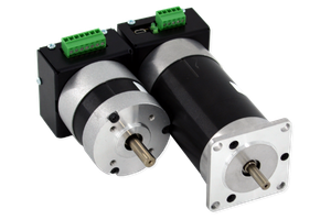
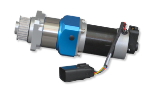
For applications where installation space, wiring, or assembly time are important, a BLDC motor with an integrated controller combines the motor and electronics into a single compact assembly. Potential advantages include reduced wiring, simplified installation, smaller system footprint, fewer external components, and easier machine integration. Integrated solutions can be particularly useful in OEM equipment where space is limited or where simplified assembly is a priority.
Customized BLDC Solutions
Not every application can be accommodated by a standard off-the-shelf brushless DC motor or controller. To close this gap, Anaheim Automation offers a variety of customization options and value-added services, including:
- Custom motor shafts
- Specialized motor windings
- Encoder integration
- Custom cables, lead wires, and connectors
- Gearbox integration
- Modified mounting configurations
- Footprint matching
- Private labeling
- Custom controller integration
Working with a motion-control component supplier capable of providing both standard components and application-specific modifications can help reduce engineering time and avoid unnecessary machine redesign.
BLDC System Selection Checklist
Before selecting a BLDC motor and controller, define the following:
Motor Requirements
- Required continuous torque
- Peak torque
- Operating speed
- Maximum speed
- Voltage
- Current
- Duty cycle
- Motor dimensions
- Shaft and mounting requirements
- Feedback requirements
- Environmental conditions
Controller Requirements
- Input voltage
- Continuous and peak current
- Motor compatibility
- Feedback compatibility
- Commutation method
- Control interface
- Open- or closed-loop operation
- Protection features
- Thermal requirements
- Physical dimensions
System Requirements
- Power supply
- Mechanical load
- Gearbox requirements
- Brake requirements
- Encoder requirements
- PLC/motion controller compatibility
- EMI considerations
- Installation environment
- Customization requirements
Choosing the Right Brushless DC Solution
Selecting a BLDC system should begin with the application, not with a particular motor or controller.
First determine the required torque, speed, voltage, current, duty cycle, feedback, mechanical configuration, and operating environment. Then select a motor and controller that can work together to meet those requirements.
For OEMs and design engineers, treating the motor and controller as a complete system can simplify component selection, improve machine performance, and reduce integration challenges.
Anaheim Automation offers a broad selection of BLDC motors, drivers/controllers, integrated motor/controller solutions, gearmotors, linear actuators, encoders, and accessories, along with customization and value-added services for application-specific requirements.