We use cookies to make your experience better. To comply with the new e-Privacy directive, we need to ask for your consent to set the cookies. Learn more.
Servo Motor Guide
Table of Contents
What is a Servo Motor?
A Servo Motor is a motor which is part of a servomechanism. It is typically paired with some type of encoder to provide positioning and speed feedback.
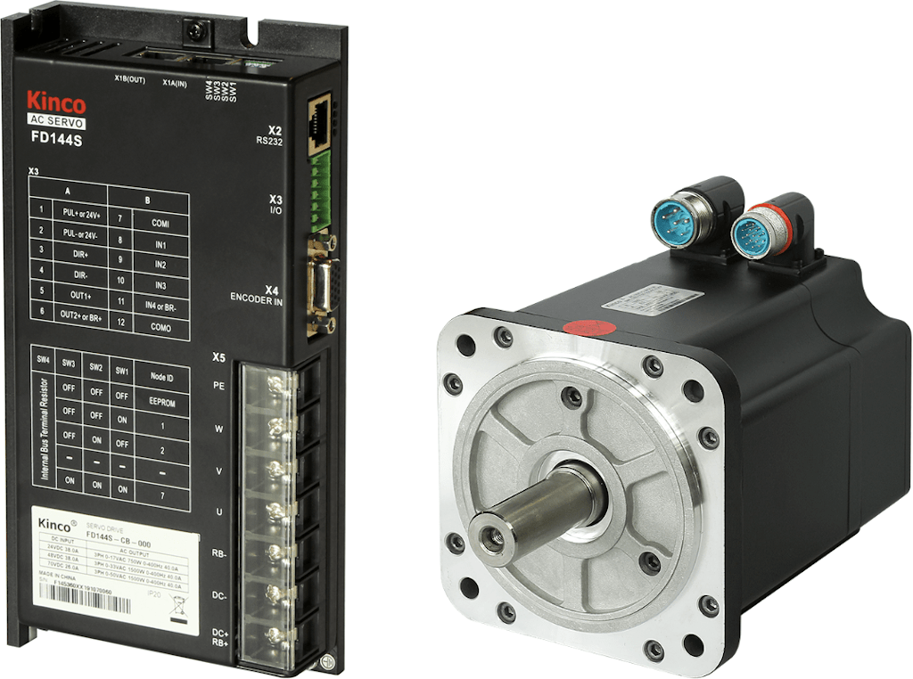
Servo drive and motor, Kinco system PKS-FD144S-12
Servo Motor Basics
A servomechanism is defined as an automatic device that uses an error-correction routine to correct its motion. The term servo can be applied to systems other than a Servo Motor; systems that use a feedback mechanism such as an encoder or other feedback device to control motion parameters. Typically when the term servo is used, it applies to a 'Servo Motor' but is also used as a general control term, meaning that a feedback loop is used to position an item.
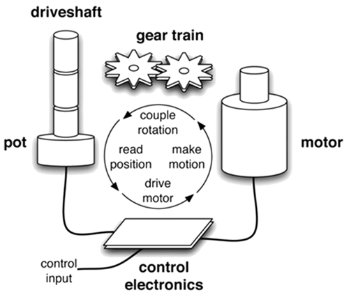
A basic servo system.
A servomechanism may or may not use a servo motor. For example, a household furnace is a servomechanism that is controlled by a thermostat. Once a set temperature is reached, there is feedback signaling it to shut off; making it a “servo” in nature. The term “servo” describes more of a function or task, than it does a specific product line. For this guide, we will specifically discuss servo motors as used in motion control applications.
A servo motor can be a DC, AC, or Brushless DC motor, combined with a position sensor; in most cases, a digital encoder. A servo motor is typically the motor selected when an application demands a high degree of confidence that the servo motor and drive system will closely track what is asked of it. There is typically a higher cost to a servo motor system than a stepper motor system, due to the servo motor’s feedback sensor and processing electronics.
Servo Motor History
The steam engine governor is considered the first powered feedback system that used a gain value, so it is considered the first servomechanism. The word Servo Motor comes from the French phrase "Le Servomoteur" or the "slave motor". The first known record of its use was by JJL Farcot in 1868 to describe steam engines and hydraulics for use in steering a ship.
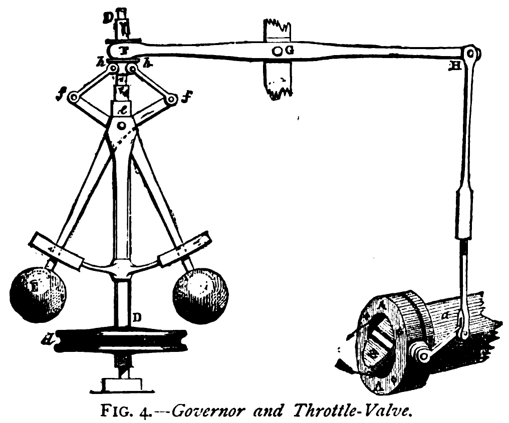
Image courtesy of Wikipedia: Drawing of a centrifugal "fly-ball" governor. The balls swing out as speed increases, which closes the valve, until a balance is achieved between demand and the proportional gain of the linkage and valve.
Physical Properties of a Servo Motor
A Servo Motor consists of two major parts: a motor and a feedback device. An encoder is the most commonly used feedback device used in servo motors. An encoder is an electromechanical device that measures position, and outputs digital signals to a controller.
The encoder allows the control circuitry to monitor the motor's current, speed, or position, enabling the controller to modify the motor's behavior. For example, in position control mode, when the angle of the servo motor shaft is correct, the controller stops the motor from turning. If the controller detects that the angle is not correct, it will turn the servo motor the correct direction until the angle is correct.
Where are Servo Motors Used?
Servos are extremely useful in robotics and automation. Servo motors are used across various automation fields, specifically where the motor must be able to operate at a range of speeds without overheating, operate at zero speed while being able to retain its load in a set position, as well as operate at low speeds.
Servo systems are commonly used in industrial machine tools, CNC manufacturing machines and processes, and packaging applications. Robots utilize servo motors because of their smooth commutation and accurate positioning. The aerospace industry makes use of servo motors in their hydraulic systems to contain system hydraulic fluid.
Servo motors are often relatively small in size, yet very powerful. A servo motor also draws power proportional to the mechanical load.
Anaheim Automation offers a range of integrated servo systems through its partnership with Kinco Automation, including the iSMK and iWMC series. These integrated servo solutions combine a servo motor, drive, and encoder into a single compact unit, simplifying installation and wiring, while reducing space requirements and system costs. The iSMK and iWMC are ideal for high-performance applications requiring accurate motion control, especially in space-constrained environments such as automated guided vehicles (AGVs), textile machines, labeling systems, and compact packaging equipment.
Read more about our iSMK and iWMC integrated servo solutions from Kinco Automation.
What Industries Use Servo Motors?
Servo motors are seen in applications such as factory automation, robotics, CNC machinery, and packaging. The feedback lets the drive know the motor's position, speed, and torque to detect unwanted motion. Biomed and Life Sciences industries are driven by the need to create ever-smaller devices, which must be easier to operate and function more efficiently than before. Servo motors and systems are often used in such devices thanks to their smooth, high-precision operation, packaged in a power-dense footprint.
Servo motors are used in a variety of automation applications across industries.
Anaheim Automation's customer base for the Servo Motor product line is diverse: companies operating or designing automated machinery or processes that involve food, cosmetics or medical packaging, labeling or tamper-evident requirements, cut-to-length applications, assembly, conveyor, material handling, robotics, special filming and projection effects, medical diagnostics, inspection and security devices, pump flow control, metal fabrication (CNC machinery), and equipment upgrades.
Many OEM customers request that we "private-label" the Servo Motor, so that their customers stay loyal to them for servicing, replacements and repairs.
Servo motors are used in a variety of automation applications across industries
Anaheim Automation's customer base for the Servo Motor product line is diverse: companies operating or designing automated machinery or processes that involve food, cosmetics or medical packaging, labeling or tamper-evident requirements, cut-to-length applications, assembly, conveyor, material handling, robotics, special filming and projection effects, medical diagnostics, inspection and security devices, pump flow control, metal fabrication (CNC machinery), and equipment upgrades.
Many OEM customers request that we "private-label" the Servo Motor, so that their customers stay loyal to them for servicing, replacements and repairs.
How Does a Servo Motor Work?
A servo motor is part of a closed-loop system, taking its commands from a servo controller, and using a feedback device that closes the loop. The motor, controller, and feedback device constitute a servomechanism. The controller sends commands to the motor, causing the motor to move, and the encoder sends feedback (information about the motor's current, speed, or position) back to the controller. The controller compares the feedback data to the commanded parameters and adjusts the motor's behavior as needed.
As previously discussed in this guide, servo motors – that is, motors that form part of a servomechanism – are very diverse. The term can be applied to small DC motors such as those used by hobbyists, as well as to advanced brushless motors used in complex machines. In a sophisticated system, the feedback device is some type of encoder, integrated into the motor. Precision encoder feedback enables real-time adjustments to match control parameters. In a very sophisticated servo system, multiple feedback loops for current (torque), speed, and position may be embedded to provide ultra high-precision motion control.
Servo Motor Feedback
There are two types of motion control systems: open-loop and closed-loop.
In an open-loop system, the input signal, which may be either analog or digital, travels through amplifiers to produce the correct output before then passing out of the system. Open-loop systems have no feedback, so the input must be returned to zero before the output can return to zero.
A closed-loop system is "self-adjusting." Rather than data flowing in only one direction, it may route back to the start of the system from a specific amplifier, such as velocity or position, instructing the system to adjust itself accordingly as necessary. The velocity and current position data modify the output and position at a consistent, predetermined rate.
There are two options for Servo Motor feedback controls, either a servo encoder or a servo resolver. A servo encoder and a servo resolver provide the same solution in many applications, but are vastly different. They are both used to sense speed, direction, and position of the Servo Motor output shaft.
The resolver on the Servo Motor uses a second set of rotor and stator coils, called the transformer, to induce rotor voltages across an air gap. A resolver does not use any electronic components, so it is very robust. Resolvers have high temperature tolerance, and are inherently shock-resistant due to their design. A resolver is mostly used in harsh environments.
There are many types of encoders that could be used in a servo motor – optical or magnetic, absolute or incremental, and more. Different encoders work differently. For example, an optical encoder uses a rotating shutter to interrupt a beam of light across an air gap between a light source and a photodetector. Alternatively, a magnetic encoder has a rotor containing alternating, evenly spaced north and south poles around its circumference, and a sensor that detects small shifts in the position N>>S and S>>N.
Different types of encoders have their respective advantages and disadvantages, depending on the application. To learn more about encoder types, refer to our Encoder Guide.
Anaheim Automation offers Kinco servo motors equipped with one of the following encoder types, dependent upon the motor model: 2,500 PPR Incremental, 20-Bit Single-Turn, 16-Bit Single-Turn Magnetic, 16-Bit Multi-Turn Absolute, or Magnetoelectric.
The application will determine whether a resolver or an encoder – and which type of encoder – is needed. Encoders are more accurate and easier to implement so they should be the first choice for any application. The only reasons to choose a resolver are environmental concerns or longevity requirements.
How are Servo Motors Controlled?
Servo motors operate on negative feedback, meaning that the control input is closely compared to the actual position via a transducer. If there is any variance between physical and wanted values, an error signal is amplified, converted, and used to drive the system in the direction necessary to reduce or eliminate error.
Servo motors are controlled by a pulse of variable width that is sent from a micro-controller output pin to the motor’s control wire. The shaft angle is determined by the duration of the pulse, also known as pulse width modulation (PWM). This pulse must have specific parameters: a minimum pulse, a maximum pulse, and a repetition rate.
Given these constraints, neutral is defined to be the position where the servo has exactly the same amount of potential rotation in the clockwise direction as it does in the counter clockwise direction. It is important to note that different servo motors will have different constraints on their rotation, but they all have a neutral position, and that position is always around 1.5 milliseconds (ms).
Anaheim Automation offers Kinco AC and DC Servo Drives providing high speed DSP (Digital Signal Processing). Kinco Servo Drives are equipped with a range of dynamic features:
High Overload Capacity
- Kinco Servo Drives can handle up to three-fold the rated power of the unit for instantaneous load requirements.
Communication Interface
- Standard CAN bus interfaces are available in the FD AC Servo Driver, simplifying the integration process. Based on Modbus protocol via RS485 interface, up to 31 servo motors can be connected together.
- When RS485 interface is used, the transmission distance can reach up to 4,000 feet. Fieldbus and EtherCAT modules are also available. Anaheim Automation Servo Drivers can also communicate with a PLC, VFD, another servo drive, HMIs/industrial touch screens, and more.
Setting up Position Control using Kinco Servo + Software
Kinco Servo+ Communication Software
Kinco Servo+ software is capable of the following:
- Parameter Management – fast and convenient operations to all parameters available, including editing, transmissions, comparison, and initialization
- Monitoring – real-time monitoring of all I/O signals, alarms of the present and history records, and system status
- Real-Time Management – real-time sampling of the torque vs. speed curves for simple, rapid analysis
- Adjusting – quick adjustment of gains, PID Control, and Target Window changes made easily
Servo Motor Types
There are two main types of Servo Motors: Rotary and Linear.
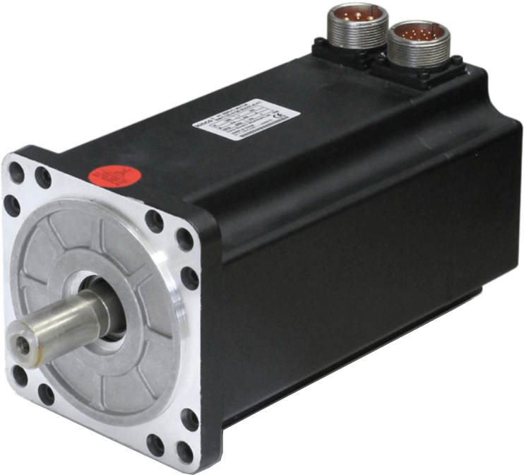
Rotary Servo Motor, Kinco SMH110D-0120-30AAK-4DKR
Rotary Servo Motor
A Rotary Servo Motor is what most people think of when they think of a Servo Motor. There are many types of Rotary Servo Motors: AC Servo Motor, Stepper Servo Motor, Brush DC Servo Motor, Permanent Magnet Synchronous Servo Motor, and Brushless DC Servo Motor. The motion of a rotary Servo Motor is often converted into linear motion by the use of a screw thread (ball screw or lead screw), or with the use of belts and pulleys.
Any motor that has a closed-loop feedback device that responds to disturbances in the motion profile classifies as a Servo Motor.
Typically, Servo amplifiers (or drivers) are coupled with Permanent Magnet Synchronous Motors that feedback speed and position through an encoder mounted to the shaft. The amplifier can also receive a feedback signal from an encoder mounted elsewhere in the application, such as on the lead screw or drive pulley, to close the loop on the motion profile.
The feedback signal changes the amount of current that the motor receives from the amplifier so that more current is delivered when the motor requires more torque, and less current is delivered when the motor does not require it. In torque control mode, the servo motor will increase and decrease voltage to maintain speed and always deliver a specified torque.
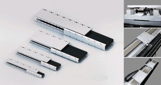
CPC LM Series Linear Servo Motors
Linear Servo Motor
A linear Servo Motor is a flattened out Servo Motor where the rotor is on the inside, and the coils are on the outside of a moveable u-channel. Both Servo Motor types are becoming more popular as Servo Motor prices continue to come down.
How to Select a Servo Motor
The simplified definition of a servo system is that it consists of several components which together control or regulate speed/position of a load. The servo motor is one of these components in the system.
When it comes time to select an appropriate servo motor for an application, some people may assume they can simply size the motor based on the horsepower rating of the presently installed motor, or exclusively based on the application's torque requirements.
On the contrary, the following factors must all be taken into account when selecting the appropriate motor:
- inertia ratio
- speed
- maximum torque at desired speed
Inertia Ratio
Any rotating object has a moment of inertia, which is a measurement of how difficult it is to change the rotating velocity of that object. Moment of inertia in a servo system can be divided into two parts: load inertia and motor inertia.
The motor inertia is part of the servo design, and is typically listed in the manufacturers' specification sheet. Load inertia is more complicated because it involves every component that is moved by the motor, and is calculated using proper equations for each component.
The load inertia-to-motor inertia is the inertia ratio of a system. For servo motor applications, Anaheim Automation recommends an inertia ratio of 30:1 or lower. The lower the ratio, the better the motor response is.
Speed and Torque
Since there may be a variety of servo motors that meet the required inertia ratio specifications, the next step is to find the smallest, most cost-effective servo motor that will meet the speed and torque demands.
Servo motor manufacturers normally provide speed-torque curves for each series of motors, which illustrate several interesting points of the servo motor's characteristics. The speed-torque curve contains two regions; continuous and intermittent, which can translate to correct match or incorrect match (respectively) for the application.
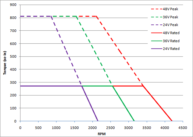
Example Torque Curve for Kinco SMC60S-0060-30MxK-5DSU motor
If the speed-torque required for a specific application falls into the continuous region of the speed-torque curve, then that motor can produce that torque and speed without overheating. If the speed-torque required for the application falls into the intermittent region of the curve, then that motor can only produce that speed and torque for a limited amount of time before overheating.
Other Factors
Be sure to consider any other environmental requirements or space constraints your application may have when selecting a motor. For example, your system may require a certain IP rating in harsher environments, or you may need an integrated system if your footprint is small.
Servo Motor Cost
A Servo Motor is considered one of the more expensive motors when compared to AC, Brushless DC, Stepper, and other motor types. The reason for the expense of a Servo Motor is the precision required to make a Servo Motor, and the added components that go along with a Servo Motor.
Generally speaking, a Servo Motor is used as a precise positioning or speed control device. The motion should be smooth and exact. To accomplish this, the Servo Motor is manufactured under very tight control parameters.
Servo motor cost is also affected by the case, bearings, connectors, and feedback devices used in construction. The case is usually industrial grade, often sealed to achieve an IP65 rating or better. The bearings are high quality to ensure that the Servo Motor can run the speeds desired and can handle the appropriate axial and radial loads. The connectors are typically mil-style connectors that can be detached at the Servo Motor, but are very reliable and industrial grade. The feedback devices are typically differential encoders and/or resolvers. These devices are very expensive and add cost to the Servo Motor.
Servo Motor Accessories
Anaheim Automation provides many different accessories for its Servo Motor product line. These accessories include brakes, encoders, connectors, cables and a handheld interface unit, as well as a full line of servo motor drives.
Many of Anaheim Automation's servo motors are available with a brake option mounted to the motor. Brake adders can also be mounted to any of our models which do not come standard with a brake already. Servo Motor brakes have a low voltage design for applications that are susceptible to weak batter, brown out, or long wiring runs. When electric power is applied to the Servo Motor brake, the armature is pulled by the electromagnet force in the magnet body assembly, which overcomes the spring action. This allows the friction disc to rotate freely. When electrical power is interrupted, the electromagnetic force is removed and the pressure spring mechanically forces the armature plate to clamp the friction disc between itself and the pressure plate.
Anaheim Automation's servo motors are equipped with one of the following encoder types, dependent upon the motor model: 2,500 PPR Incremental, 20-Bit Single-Turn, 16-Bit Single-Turn Magnetic, 16-Bit Multi-Turn Absolute, or Magnetoelectric.
Anaheim Automation's Servo Motors come with the necessary connectors to connect to another company's servo drive or an Anaheim Automation servo drive. These Servo Motor connectors can also be purchased separately should they become lost. Please refer to the servo motor user's guide for a specific part numbers.
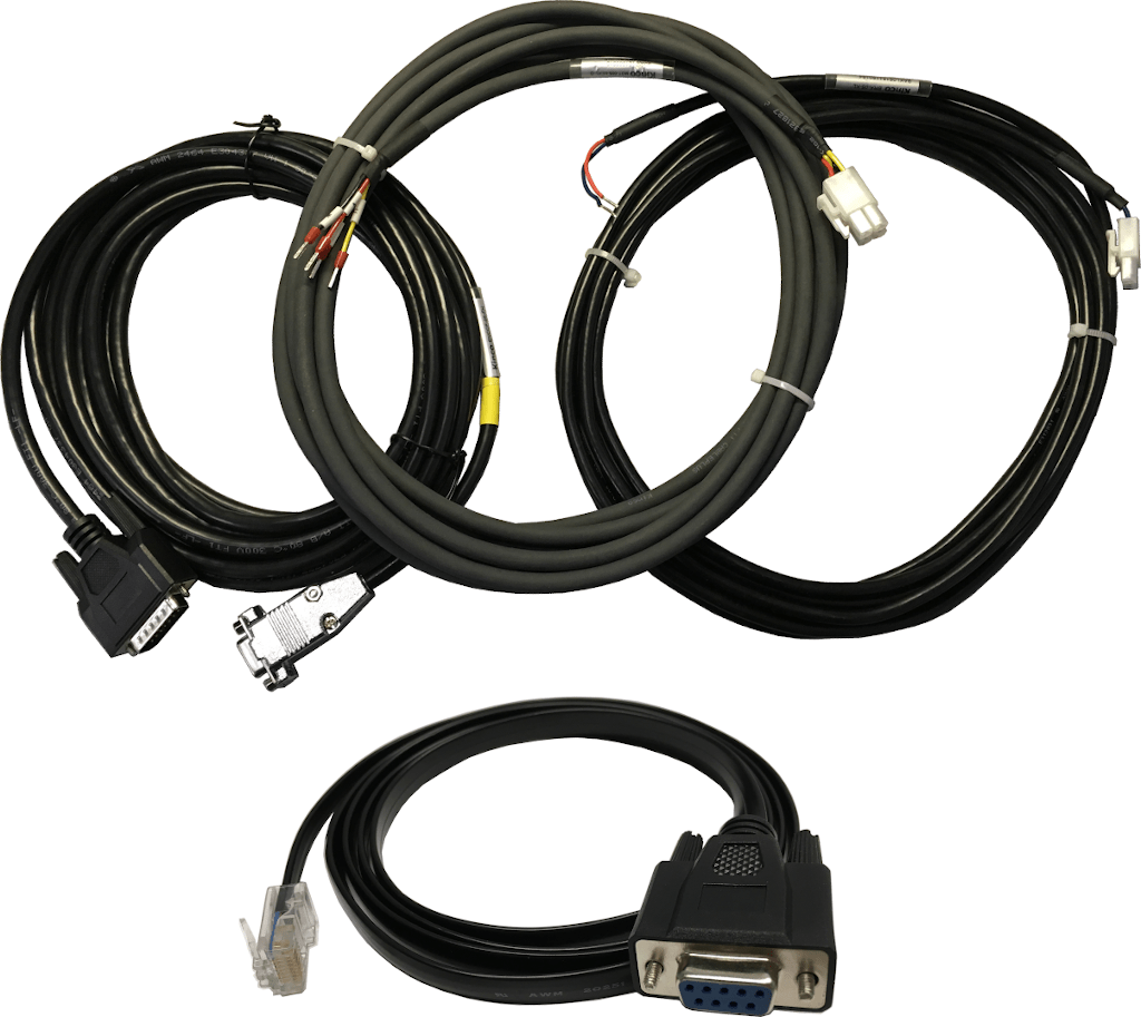
Kinco servo cables
Servo Motor cables can be made with the supplied Servo Motor connector, or can be purchased from Anaheim Automation. The Servo Motor cable comes with a standard length of 5M but can be adjusted to any length required.
Note: Anaheim Automation strongly recommends the purchasing of the cables with servo motors and drives to ensure cable integrity. These cables are perfectly matched, and provide a stable connection.
Servo Motor Customization
Anaheim Automation was established in 1966 as a manufacturer of "turnkey" motion control systems. Today, Anaheim Automation ranks among the leading manufacturers and distributors of motion control products; a position enhanced by its excellent reputation for quality products at competitive prices. The Servo Motor product line is no exception.
Anaheim Automation offers a wide variety of standard Servo Motor products. Occasionally, OEM customers with mid to large quantity requirements prefer to have a Servo Motor that is custom or modified to meet their exact design requirements.
Sometimes the customization is as simple as a shaft modification, brake, oil seal for an IP65 rating, mounting dimensions, wire colors, or simple label requirement. Other times, a customer might require that a Servo Motor meet an ideal specification such as, speed, torque, and/or voltage.
Engineers appreciate that Anaheim Automation's Servo Motor product line can answer their desire for creativity, flexibility and system efficiency. Buyers appreciate the simplicity of the "one-stop shop," and the cost savings of a custom Servo Motor design.
Note: Special/custom orders typically require an MOQ (minimum order quantity) and/or NRE (Non-recurring Engineering Fee).
Anaheim Automation's standard Servo Motor product line is a cost-effective solution known for rugged construction and excellent performance. Our wide range of standard servo motors is stocked in Anaheim, California, USA. Hundreds of models are on hand, ready to ship. For R&D and other lower quantity requirements, view pricing (including quantity discounts), stock status, and shop online.
Should you need assistance, Contact Us – our applications engineers are ready to offer their expertise, and our friendly customer service representatives are prepared to help you in any way they can.
All sales for a customized or modified Servo Motor are Non-Cancelable, Non-Returnable, and an NCNR Agreement must be signed by the customer, per each request. All sales, including a customized Servo Motor, are made pursuant to Anaheim Automation's standard Terms and Conditions, and are in lieu of any other expressed or implied terms, including but not limited to any implied warranties.
Technical Assistance
Technical assistance regarding its Servo Motor product line, as well as all the products manufactured or distributed by Anaheim Automation, is available at no charge. This assistance is offered to help the customer in choosing Anaheim Automation products for a specific application.
However, any selection, quotation, or application suggestion for a Servo Motor, or any other product, offered from Anaheim Automation's staff, its representatives, or its distributors, is only to assist the customer. In all cases, determination of fitness of the Servo Motor in a specific system design is solely the customers' responsibility.
While every effort is made to offer accurate advice regarding the Servo Motor product line, as well as other motion control products, and to produce technical data and illustrations accurately, such advice and documents are for reference only, and subject to change without notice.
Anaheim Automation is in no event responsible or liable for indirect or consequential damages resulting from the use or application of the Servo Motor. Improper use of a Servo Motor in an application can result in personal injury or death, property damage, and/or economic loss. Persons not familiar with servo motor systems installation might be better served to use a qualified systems integrator.
Servo Motor Environmental Considerations
Environmental and safety considerations must be observed during all phases of operation, service, and repair of a Servo Motor system. Failure to comply with these precautions violates safety standards of design, manufacture, and intended use of the Servo Motor and Drive.
The atmosphere in which a Servo Motor is used must be conducive to good general practices of electrical/electronic equipment. Do not operate the Servo Motor in the presence of flammable gases, dust, oil, vapor, or moisture.

Avoid Flammable Gas, Dust, Oil, and Vapor
Please note that even well-built servo motor products operated or installed improperly can be hazardous. Precaution must be observed by the user with respect to the load and operating environment.
For more information on environmental considerations for Servo Motors, Systems, and other motion control components, please refer to our Installation and Environment Guide. This guide provides helpful tips and best practices for keeping people and equipment safe.
Note: Meeting CE Requirements for a servo motor and drive system requires a ground system, and the method of grounding the AC line filter and the servo motor drive must match. Failure to do this renders the filter ineffective and may result in damage. For grounding and filter suggestions, please Contact Us.
Servo Motor Mounting and Installation
Safety
Human safety and equipment safety must be the first considerations when performing the installation procedures for the servo motor and drive system. When it comes to electronics in your factory or workplace, you want to make sure both your facility and the employees in it are safe. Please review the Safety section of our Installation and Environment page for a basic best-practices checklist for electrical safety.
Mounting — Overview
Proper installation will achieve the best results from the production capability of the servo motor and drive system. This can only be accomplished if several important steps are implemented and some precautions are taken. Note: Local codes may suggest different requirements, but those given in this section must be satisfied as much as possible.
Caution: only qualified personnel should be allowed to open and work on the servo motor and drive and other components inside electrical enclosures.
Equipment and machinery should never be run unless the electrical enclosure door is closed and locked.
The electronics inside the main electrical enclosure are sensitive to metal chips and filings. During the installation and use of the servo motor and drive system, great care must be given to make sure metal chips or filings cannot fall onto or into any of the electrical devices.
Electrical Installation
Safety is the number one concern when performing the electrical connection of the servo motor and drive, as well as all motion control products and electrical equipment. Therefore, check every step at least once after it has been taken.
During the installation of the servo motor and drive, it is important to minimize the possibility of electrical noise (an unwanted disturbance in an electrical signal, caused by natural or man-made sources) entering critical sensitive circuits. This is best accomplished by following the electrical installation procedures precisely, as detailed in the product's users' manual.
Considerable attention has been given to noise immunity in the basic design and manufacture of the servo motor and drive system. However, it is essential that great care and attention be given during the installation of the equipment in your machine or in your facility.
Plan Ahead
Before attempting any electrical installations, gather any drawings, instructions, or procedural documents you have on the servo motor and drive, as well as other components in your system. Reading and studying the product documentation before starting the project will alert you to any special situations, such as the need for specific tools. Always keep the specific product documentation with you while completing the installation, as you should regularly refer to it.
Documentation among servo motor and drive manufacturers will vary greatly, as their design, layout, and connections are not the same. Match the part numbers to the documentation before attempting the installation. Even seasoned professionals need guidance and advice while performing complicated electrical installations. This ensures the safest results for everyone.
Mounting, Bonding and Grounding your Servo System
After establishing all layouts, you can begin mounting, bonding, and grounding each chassis/enclosure. Bonding is the connecting together of metal parts of chassis, assemblies, frames, shields, and enclosures to reduce the effects of EMI (electromagnetic interference) and ground noise. Grounding is the connection to the grounding-electrode system to place equipment at earth ground potential.
Please refer to the Mounting, Bonding and Grounding section of our Installation and Environment page for more detailed information on best practices for mounting, bonding, and grounding of motion control systems, such as servo motors and drives.
Important note: These guidelines assume that you follow surge-suppression guidelines. While these guidelines apply to the majority of servo motor and drive installations, as well as other motion control applications, certain electrically harsh environments may require additional precautions.
Understanding EMI – Electromagnetic Interference
Electromagnetic Interference is the radiation or induction of electromagnetic noise on a system or machine. Servo motors, and motors in general, are a common source of EMI, due to their electromagnetic circuit components. An electromagnetic disturbance which may degrade the performance of equipment (device, system or sub-system), or causes malfunction of the equipment, is called electromagnetic interference (EMI).
EMI can be radiated from magnetic sources or conducted from electrical sources. In the case of most motors, both radiated and conducted emissions are present. Electrical noise is always present in an electrical system.
Possible Effects of EMI in a servo motor and drive system:
- Intermittent disturbances in the servo drive and controllers
- Computers and HMIs may falter and lose data, causing reset/start-up
- Burn-out of sensitive components
- Disturbance in the settings and status registers of the control equipment
- Decreased productivity
Motors are potential sources of noise and can generate common-mode currents. EMI can result in degraded system performance and/or data corruption. When it is very strong, it can cause the system to fail completely.
EMC – Electromagnetic Compatibility
Electromagnetic Compatibility is the practice of monitoring and reducing unwanted EMI.
Electromagnetic compatibility describes a near-perfect state in which a receptor (device, system, or sub-system) functions well in a common electromagnetic environment, without introducing intolerable electromagnetic disturbance to any other devices, equipment or systems that share the environment.
Proper cable selection and shielding are essential – always make certain to use a shielded cable with the correct number of wires which has been securely grounded at either the motor or drive.
Be sure to keep the cables as short as possible, preventing them from coiling/looping around themselves.
Keep as much distance between any communication cables and high-voltage (power) cables as possible.
Following these guidelines will help to minimize electrical noise in your system.
Important note: EMC is an important field in electronics with strict regulations. Motors and their circuits are significant sources of EMI. It is essential that engineers/system designers take the appropriate actions to reduce EMI and improve EMC as much as possible.
EMI is a dense and complicated topic. For more information on EMI, including typical sources of EMI, EMC and EMI reduction techniques, and a best-practices checklist, please refer to our EMI Guide.
Surge-Suppression – General Practices
Transient Electromagnetic Interference (EMI) can be generated whenever inductive loads such as relays, solenoids, motor starters, or motors are operated by “hard contacts” such as pushbutton or selector switches. The wiring guidelines are based on the assumption that you guard your system against the effects of transient EMI by using surge-suppressors to suppress transient EMI at its source.
Inductive loads switched by solid-state output devices alone do not require surge-suppression. However, inductive loads of AC output modules that are in series or parallel with hard contacts require surge-suppression to protect the module output circuits, as well as to suppress transient EMI.
Electrical noise from any source, whether it is the power line, an electrical arc generated in an adjacent machine or process, or crosstalk within the control, is transmitted by conduction, inductive, or capacitive coupling, or radiation. It is extremely important to maintain the electrical enclosures and panels, conduits, wiring shields, and machine members at zero potential, and to provide a return path to the earth for noise currents, in order to effectively shield the sensitive logic from electrical noise.
Sizing the Transformer — General Practices
Transformers are often useful in powering servo systems. A transformer is a component that transfers electrical energy from one electrical circuit to another, or to multiple other circuits. Transformers allow electrical energy to transfer between separate coils without a metallic (conductive) connection between the two circuits.
Transformers are most commonly used to change voltage levels of AC circuits – increasing low AC voltages at high current, or decreasing high AC voltages at low current – and for voltage isolation.
To determine the required rating of the transformer, add the external-transformer load of the power supply and all other power requirements (input circuits, output circuits). The power requirements must take into consideration the surge currents of devices controlled by the processor.
Choose a transformer with the closest standard transformer rating above the calculated requirements. For example, a 500VA transformer should be used if there were 360VA of load.
Isolation Transformer — for applications near excessive electrical noise generators, an isolation transformer (for the second transformer) provides further suppression of electromagnetic interference (EMI) from other equipment.
Constant-Voltage Transformer — in applications where the AC power source is especially “soft” and subject to unusual variations, a constant-voltage transformer can stabilize the AC power source to the processor and minimize shutdowns. The constant-voltage transformer must be of the harmonic neutralizing type.
If the power supply receives its AC power through a constant-voltage transformer, the input sensors connected to the I/O chassis should also receive their AC power from the same constant-voltage transformer.
The output actuators being controlled should draw power from the same AC sources as the constant-voltage transformer, but not from the secondary of the constant-voltage transformer.
Warning: Dangerous voltages capable of causing injury or death may be present in the Servo Motor system. Use extreme caution when handling, testing, and adjusting during installation, set-up, tuning, and operation. It is very important that the wiring of the Servo Motor be taken into consideration upon installation and mounting.
Subpanels
Subpanels installed inside the enclosure for mounting Servo Motor system components, must be a flat, rigid surface that will be free from shock, vibration, moisture, oil, vapors, or dust.
Remember that the Servo Motor and drive will produce heat during work. Therefore, heat dissipation should be considered in designing the system layout. Size the enclosure so as not to exceed the maximum ambient temperature rating. It is recommended that the servo drive be mounted in an upright position, providing adequate airflow. The Servo Motor should be mounted in a stable fashion, secured tightly.
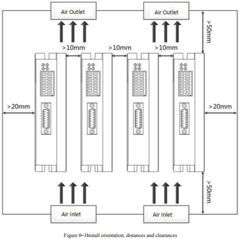
A diagram from the User Manual for Kinco Automation's FD4S servo system showing proper installation orientation, distances, and clearances of the controller to ensure sufficient convection air flow through the enclosure.
There should be a minimum of 10mm between the servo drive and any other devices mounted in the system/electric panel or cabinet. There should be at least 10mm space in the lateral direction and 50mm space in the longitudinal direction, between the servo motor drive and other electronic/electrical devices. For multi-axis systems, mount in the panel left to right according to power utilization (highest to lowest). If power utilization is unknown, mount from left to right based on Amp rating.
In order to comply with UL and CE requirements, the servo motor drive must be grounded in a grounded-conducive enclosure offering protection as defined in standard EN 60529 (IEC 529) to IP55 such that they are not accessible to the operator or unskilled person. As with any moving part in a system, the Servo Motor should be kept out of the reach of the operator. A NEMA 4X enclosure exceeds those requirements providing protection to IP66.
To improve the bond between the power rail and the subpanel, construct your subpanel out of zinc-plated (paint-free) steel. Additionally, it is strongly recommended that the servo motor drive be protected against electrical noise interferences. Noise from signal wires can cause mechanical vibration and malfunctions.
Servo Motor Wiring — Safety First!
Extension Cord Safety
When installing new technology, you may be dealing with extension cords to help plug your products on a test bench for prototyping. Use them on a temporary basis. Extension cords are not meant for permanent wiring.
Here are some general electrical cord safety tips when dealing with extension cords, in part, courtesy of the Electrical Safety Foundation International, which develops safety policies and procedures for electronics.
Extension Cords:
- Should not be used as a substitute for permanent wiring.
- Should not be used with any equipment which draws over 15 Amps.
- Should not run through, behind, or inside of walls, ceilings, or floors, nor in any other inaccessible area or concealed space.
- Should not be run through ventilation ducts, underneath flooring, under doors, or in other locations where they may be subjected to abrasion or damage.
- Can be a tripping hazard, and so they should not be placed in high-traffic areas such as walkways or doorways.
- Should not be spliced or taped, nor should broken, frayed, or otherwise damaged cords be used to power Anaheim Automation products.
- Should not be used near flammable/combustible materials, gases, vapors, or explosive dusts.
- Should not be overloaded.
Note: Water and electricity don't mix: never leave plugged-in electronics where they might come into contact with water. If they do fall into water, never reach in and pull them out, even if they are turned off — electricity may still be flowing. First, turn off the power source and then unplug the unit. If you have a servo motor, drive or controller that has gotten wet, don't use it until it has been checked by our qualified repair staff.
Electrical Safety in the Workplace
When establishing electrical safety policy in the workplace, here are some points to consider, in part, courtesy of the Electrical Safety Foundation International:
- Have a good idea of and be prepared for what could go wrong.
- Always use the correct tools for the job.
- Always follow procedures, instructions, drawings, and other product documentation.
- Isolate equipment from energy sources.
- Identify hazards that may be present.
- Establish approach limitations to machinery and moving parts to minimize hazards.
- Only properly trained individuals should handle equipment.
- Work on the servo motor and/or drive (as well as any and all other Anaheim Automation products or electrical equipment) only after the equipment is de-energized.
- Check and double-check safety regulations and product documentation.
- Treat de-energized equipment as energized until a lockout/tagout test (a test used to disable machinery or equipment to prevent the release of potentially hazardous energy while the machine is being serviced) has been performed.
Why So Many Electrical Safety Requirements?
Organizations such as OSHA, in their Electrical Safety in the Workplace manual, outline the steps companies must take to be in federal compliance with safety. They include:
- A safety program with defined responsibilities
- Calculations for the degree of an arc flash hazard
- Electrical safety equipment for workers
- Training for workers
- Electrical safety tools
- Electrical safety labels on equipment
An emphasis on safety is largely due to the fear of the damage an arc flash can do. An arc flash is a short circuit through the air that can happen when conductors can't support the voltage. An arc flash can be as hot as 5,000 F and creates a brilliant flash of light and loud noise.

Arcing
As radiant energy explodes out of the electrical equipment, hot gases and melted metal can endanger human life. This is why there electrical safety standards and requirements in place to protect workers against arc flashes, and electrical safety equipment on the market in the form of boots, suits, gloves and more.
It is the responsibility of the installer/user of servo motors and drives, and all other Anaheim Automation products, to become familiar with all safety requirements. This guide is not exhaustive, and does not constitute adequate safety education for those who will work with electrical equipment.
Avoid Working with Live Wires
A “live” wire is one that has electricity running through it. If you are installing or repairing anything electrical, always isolate the equipment from the power source. In addition to turning any circuit breakers off, it is always good to test any circuit or conductor before you touch it. This can be done very simply with a hand-held voltage tester. Use this multi-meter every time you must handle something that is potentially live.
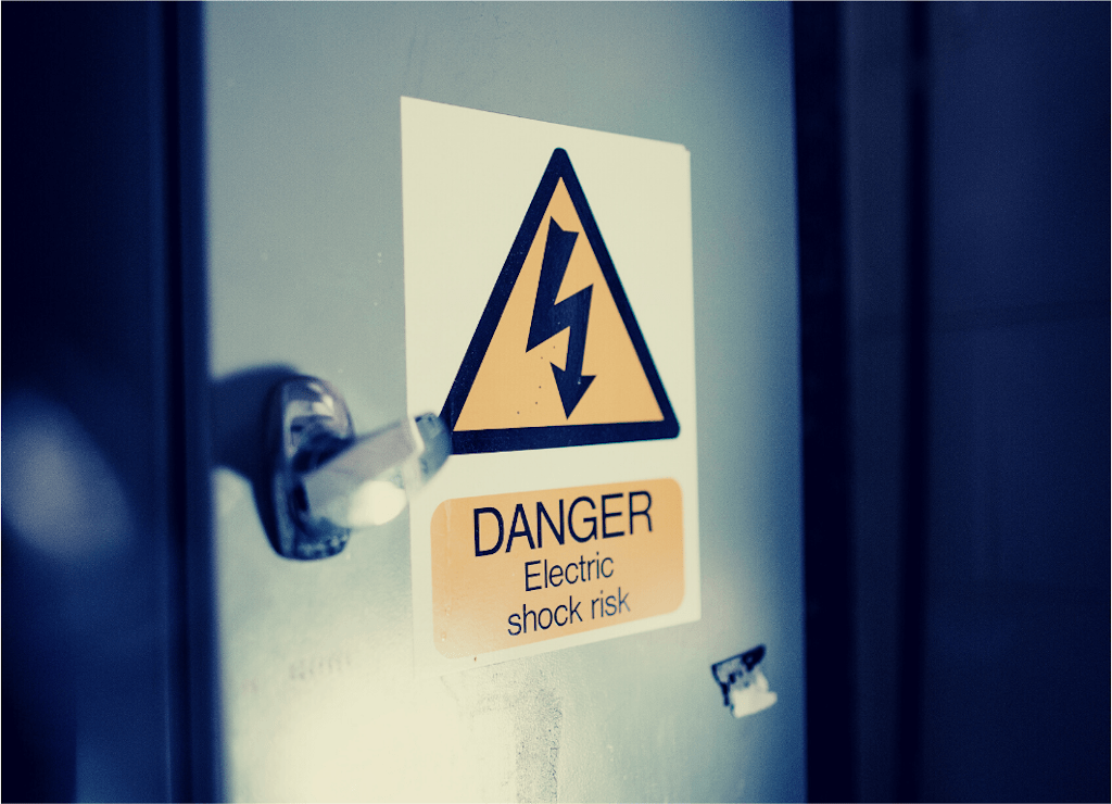
Danger Electric Shock Risk
Electrical Hazards
The following are the four main hazards involved with the installation of electrical equipment:
- Electric Shock – an electric shock or burn occurs when an electric current comes into contact with the skin and conducts through the body. If high-voltage electricity runs through the head or chest, death can occur instantly.
- Arc Flash Burn – an arc flash occurs when a conductive object gets too close to a high-voltage, electrified object. This flash can cause intense heat in the surrounding air, possibly causing clothes to catch fire.
- Arc Blast Impact – when a metal object triggers an arc flash, a subsequent blast can cause hearing loss and concussion. Also, this blast can cause lacerations from flying metal pieces or other debris.
- Falling – shocks and arc blasts can easily knock a worker off a high platform, such as a ladder or pole.
Qualified Professionals Only
Electrical wiring is complicated and potentially life-threatening if installed incorrectly. Do not attempt to install a servo motor and drive, or any other Anaheim Automation product, or other electrical equipment, unless you are certain you have received the proper training and education for the task. This is one area of business you can't afford to be frugal about. If you are not sure how to do the servo motor and drive installation, always hire a qualified electrician/panel builder/integrator. A servo motor and drive should never be used around water, dust, or flammable materials. Adherence to proper safety guidelines can save lives and valuable property by preventing electric shock and fires.
Proper Tools
When installing and wiring a servo motor and drive, it is important to use the proper tools. A non-conductive tool will have a rubber grip for you to hold it by. Never use a solid metal tool for installation, even if you are wearing gloves and have the power source turned off. There is no such thing as being too cautious when it comes to electrical shock or burns.
High-Temperature Applications – Use Braided Sleeving
The life of a cable can be greatly extended with high-temperature braided sleeving. Braided sleeving is a protective cover for the vulnerable material on common wires. High temperatures can cause cracks or frays, even fires, without braided sleeving, especially in wires and cables that are used in industrial settings or exposed to outdoor elements.
In addition to protecting the wires from high temperatures, braided sleeving can shield wires and cables from abrasions, chemicals, dirt, and even freezing temperatures. Consult with your representative should your servo motor and drive application involve high temperatures.
Shielded I/O Cables — General Practices
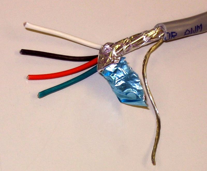
Image source: Wikipedia
Certain I/O connections require shielded cables to help reduce the effects of electrical noise coupling. Shielding (electrical noise abatement) is a complicated subject, but the following guidelines should generally apply to servo motor system installations:
- Ground each shield at one end only. A shield grounded at both ends forms a ground loop, which can cause a processor to fault.
- Never connect a shield to the common side of a logic circuit, as this would introduce noise into the logic circuit.
- Connect each shield directly to a chassis ground.
- For some communication network cables, the shield connections are unique to the particular cabling system. In some such cases, a DC short to ground is not needed because a low-impedance AC path to ground and a high-impedance DC path to ground are provided internally at each node.
- Follow the specific instructions in the manufacturer's publication provided for each specific product.
Basic Electrical Safety Rule(s)
The OSHA regulation regarding electrical safe practices states two very important basic points. The first is that live parts shall be de-energized before working on or near them. The second point is that even after the exposed parts have been de-energized, they shall still be treated as energized until they are locked out and/or tagged out. That is why the BASIC RULE for electrical safe practices procedure is stated as follows:
All electrical circuit conductors, bare or insulated, must be treated as though they are energized until proven otherwise. They must be de-energized, locked out, and tested for the absence of voltage before working on them or working near them. Work on electrical circuit conductors may only be performed by qualified personnel who have been authorized to do the work.
For persons unfamiliar with servo motor and drive products, as well as other motion control components, Anaheim Automation recommends consulting with a systems integrator for all installations.
Guidelines for Wiring Anaheim Automation Servo Motor Systems
Warning: Dangerous voltages capable of causing injury or death may be present in the servo motor driver. Use extreme caution when handling, wiring, testing, and adjusting during installation, set-up, tuning, and operation.
To avoid the possibility of electrical shock, perform all mounting and wiring of the servo motor and drive system prior to applying power. Once power is applied, connection terminals may have voltage present, even when the servo motor and drive are not in use.
- Be aware that when you route power and signal wiring on a machine or system, radiated noise from the nearby relays, transformers, and other electronic devices can be induced into servo motor and encoder signals, input/output communications, and other sensitive low voltage signals. This can cause systems faults and communication errors.
- Factory made cables are recommended for use in our Servo Motor and drive systems. These cables are purchased separately, and are designed to minimize EMI. These cables are recommended over customer-built cables to optimize system performance and to provide additional safety for the servo motor system and the user.
- Route high-voltage power cables separately from low-voltage power cables.
- Segregate input power wiring and servo motor power cables from control wiring and motor feedback cables as they leave the servo drive. Maintain this separation throughout the wire run.
- Use shielded cable for power wiring and provide a grounded 360° clamp termination to the enclosure wall. Allow room on the sub-panel for wire bends.
- Make all cable routes as short as possible.
- Single-point grounding is required when mounting the servo motor and servo drive, and grounding resistance should be lower than 100Ω.
- Applying a power input noise filter between servo drive and servo motor is prohibited.
- Do not make extreme adjustments or changes to the servo motor drive parameters, which can cause mechanical vibration and result in failure and/or loss.
- Once the Servo Motor is wired, do not run the servo drive by switching On/Off the power supply directly. Frequent power On/Off switching will cause fast aging of the internal components in the servo drive, which will reduce the lifetime of servo motor system. It's required to use reference signals to control the running of the servo motor drive.
Required Maintenance for a Servo Motor
Servo Motors are not prone to wear over time, and therefore require little maintenance. However, periodic maintenance checks should be performed so that the servo motor keeps running like new.
Upon first arrival of the servo motor, inspect the motor and verify the following:
- the motor is the correct model
- the motor does not have any visible damage
- the shaft can be rotated by hand
- the brake works correctly
- there are no loose bolts
Operators should periodically check the motor for vibration and noise while the motor is not rotating, rotating at low speeds, and accelerating and decelerating.
Inspect the motor for scratches or cracks on the motor casing. If crevices or cracks are found on the motor, action should be taken immediately by repairing or replacing the damaged unit. Check the motor casing for oil or cutting fluid because this can corrode the coating – possibly leading to future failure.
Use an insulation level tester to check insulation resistance between motor coil and motor frame, and refer to the owner’s manual to see if insulation value falls within an operable range.
Observe the normal voltage waveforms on an oscilloscope periodically and take notes for future comparison purposes and report any inconsistencies to manufacturer.
Check cables and wiring for cracks and frays. Replace if found worn, as this could be dangerous (See the Wiring section in this guide for more details).
Servo Motor vs. Stepper Motor Comparison
| Servo Motor vs. Stepper Motor | |
|---|---|
| Servo Motor Advantages | Stepper Motor Advantages |
|
High output: Power in relation to the servo motor size and weight High-efficiency: Can approach 90% efficiency at light loads High Torque to Inertia Ratio: Can rapidly accelerate loads Has 2-3 times continuous power for short periods Has 3 times rated torque for short periods Stays cool because the current draw is proportional to load Maintains usable high speed torque at 90% of no load RPM Performs quietly at all speeds Resonance-free and vibration-free operation Able to resume operation after overload or stall condition |
Stability: A stepper motor can drive a wide range of frictional and inertial loads Does Not Require Feedback: The stepper motor also acts as the position transducer Price: Relatively inexpensive Standardized: NEMA standard frame size and performance Plug and Play features: Easy to set up and use Safety: The stepper motor stops if there is a malfunction or interference Excellent Low Speed Torque: The stepper motor has the ability to drive several loads without gearing Repeatability: Accurately returns to the same location — open loop system Overload safe: A mechanical overload cannot damage the stepper motor |
| Servo Motor Disadvantages | Stepper Motor Disadvantages |
|
Higher cost in most cases Requires "tuning" to stabilize feedback loop Safety circuits are required; motor "runs away" when something breaks More complex and requires an encoder Peak torque is limited to a 1% duty cycle Sustained overload can damage the motor Power supply current 5 times average to use peak torque Develops peak power at higher speeds; gearing is often needed |
Low Efficiency: A stepper motor draws rated power regardless of the load Torque drops quickly with speed Requires microstepping to move smoothly; prone to resonance problems There is no feedback to indicate missed steps Low torque-to-inertia ratio; cannot accelerate loads very quickly In high-performance configurations, can get extremely hot (requires heat sink or fan-cooled installation) Does not "pick up" after momentary overload or stall At moderate to high speeds, the stepper motor can be noisy, which limits its applications Low output power relative to size and weight |
Formulas for a Servo Motor
Formulas for Operating Patterns
Determine the relationship between time and speed for each item that is being controlled, then convert the operating pattern for these items into a servo motor shaft operating pattern.

Triangular Operating Pattern for Servo Motor
Triangular Operating Pattern
Maximum Speed:

Acceleration/Deceleration Time:

Travel Distance:


Trapezoidal Operating Pattern for Servo Motor
Trapezoid Operating Pattern
Maximum Speed:
Acceleration/Deceleration Time:
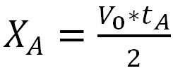
Total Travel Time:
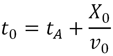
Constant-Velocity travel time:

Total Travel Distance:

Acceleration/Deceleration Travel Distance:

Constant-Velocity travel time:

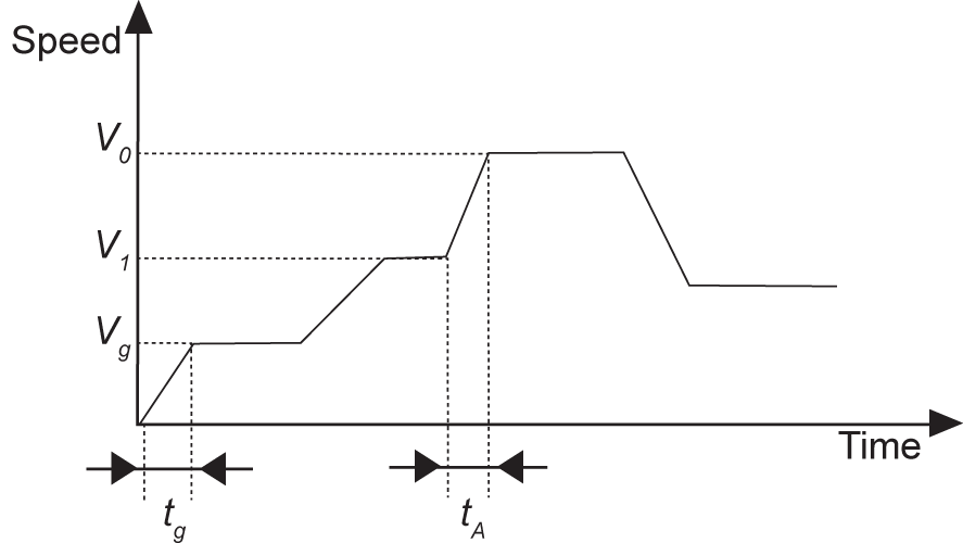
Speed and Slope when Ascending Operating Pattern for Servo Motor
Speed and Slope When Ascending Operating Pattern
Ascending Time:
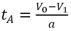
Ascending Time (tA) including distance moved:

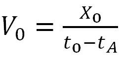
Speed after ascending:

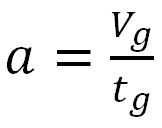
Speed Gradient:
