


.png)
What is a Magnetic Encoder?
A magnetic encoder is a sensor of mechanical motion, which in turn generates digital signals in response to mechanical motion. As an electro-mechanical device, an encoder is able to provide motion control system users with information concerning position, velocity and direction. A magnetic encoder operates by using a simple magnetized rotor disk with a flux pattern. By reading the change of flux, a magnetic encoder is able to generate signal output to the user. A linear magnetic encoder operates by using a magnetic sensor readhead and a magnetized scale. The sensor detects the change in magnetic field and generates a corresponding output signal.
Block Diagram for a Magnetic Encoder

Figure 1: Magnetic Encoder (shown in black) attached at the end of a dual shaft motor
Physical Properties
Linear Magnetic Encoders
The linear magnetic encoder system consists of a readhead, self-adhesive magnetic scale and sensor of the magnetic field. The sensor can be either a sense-coil, a Hall-Effect to detect change in voltage or a magneto-resistive read-head to detect the change in the magnetic field. There is also signal conditioning circuitry incorporated in the design to determine speed and direction.
Rotary Magnetic Encoders
The key components of a rotary magnetic encoder are the magnetized rotor and sensory circuitry. The sensory circuitry is either a Hall-Effect to detect the change in voltage or a magneto-resistive, which use resistors sensitive to change in the magnetic field. The signal conditioning circuitry is used to determine the speed and direction of the rotor.
How does a Magnetic Rotary Encoder Work?
A magnetic encoder uses two main components to provide position feedback. The first component is the rotor which is magnetized with north and south poles that are lined around the perimeter of the disk. The second component is the sensor. Two widely used sensors are the Hall-Effects sensors or the magneto-resistive sensors. The Hall-Effect sensor is able to detect the change in voltage due to the magnetic deflection of the electrons, while the magneto-resistive sensors use resistors sensitive to change in magnetic field. The sensor then creates a sine-wave output, which then is converted to a square-wave output. The magnetized rotor is attached to a shaft, therefore both turn in unison. There is an air gap between the sensory circuit and the magnetized rotor. As the rotor turns and hovers over the sensory circuitry, a sine wave signal is generated due to the change in magnetic field. The sine wave created is then converted into a square wave signal and fed to a driver or controller.
The number of magnetized pole pairs on the wheel pole, the number of sensors, and the type of electrical circuit, all work together to determine the resolution of the magnetic encoder.
Note: Hall-Effect sensors are the lower cost option in detecting magnetic field deflection, but are less precise to magneto-resistive sensors, and are more prone to jitter (signal noise).
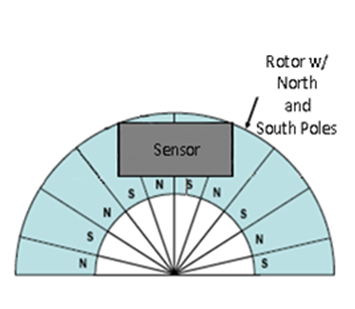
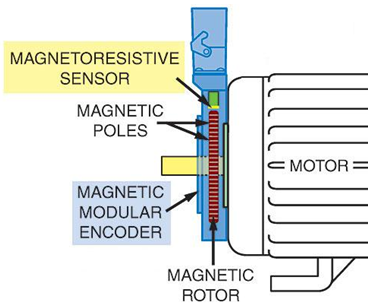
Figure 2: Magnetized Rotor Figure 3: Magnetic Encoder Mounted on Motor
How do Linear Magnetic Encoders Work?
A Linear Magnetic Encoder system uses a magnetic sensor readhead and a magnetic scale to produce TTL or analog output for Channel A and B. As the magnetic sensor passes along the magnetic scale, the sensor detects the change in magnetic field and outputs a signal. This output signal frequency is proportional to the measuring speed and the displacement of the sensor. Since linear magnetic encoders detect change in the magnetic field, the interference of light, oil, dust, and debris have no effect on this type of system; therefore they offer high reliability in harsh environments.
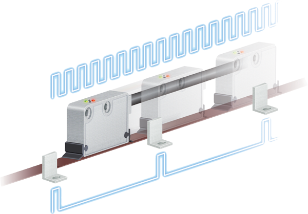
Figure 4: Linear Magnetic Encoder System
Basic Types of Magnetic Encoders
Linear Magnetic Encoders
Linear magnetic encoders are used in linear distance applications. They implement magnetic areas on a scale which is detected by a sense-coil, Hall-Effect or magneto-resistive read-head. When magnetic fluctuation is detected, a sine-wave output signal is created, which is then converted into a square wave. Linear magnetic encoders are not as precise as linear optical encoders, however they are less susceptible to dirty and humid environments which can damage optical encoders.
Rotary Magnetic Encoders
Rotary magnetic encoders are used in applications involving circular motion. These types of encoders can be attached to motors, or any shaft, for feedback control purposes. The rotor is magnetized with north and south poles. There is an air gap between the magnetized rotor magnet and the sensory circuitry. As the rotor turns and hovers over the sensory circuitry, a sine-wave signal is generated due to the change in magnetic field. The sine wave created is then converted into a square wave signal. This type of sensing method is more sensitive to the pickup of the change of the magnetic field, therefore it can allow up to 8000+ PPR (model dependent).
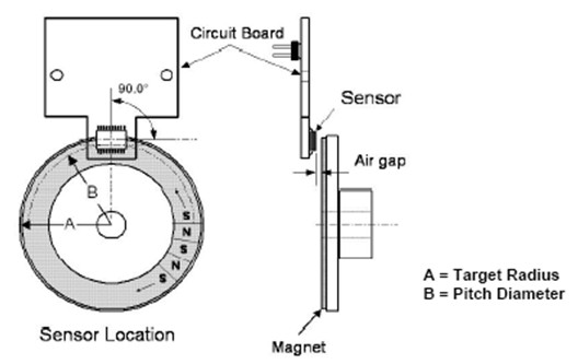
Figure 4: Magnetic Encoder
How are Encoders Controlled?
Magnetic encoders are controlled through the rotation of the shaft to which it is mounted. The rotor of the magnetic encoder is secured around a shaft. As the shaft rotates, it causes the rotor to rotate across the sensor circuitry of the encoder. The circuitry of the encoder contains either a Hall-Effect or a magneto-resistive sensor. The sensor generates a signal when detecting a change in the magnetic field. The speed at which the rotor rotates will be dependent on the speed of the shaft.
Where are Magnetic Encoders Used?
Magnetic encoders have become a vital tool for many applications requiring feedback information. Whether an application is concerned with speed, direction or distance, a magnetic encoder's vast capability provides users information required for precise control. With the emergence of higher resolutions, ruggedness and lower costs, encoders have become the preferred technology in many motion control applications.
Anaheim Automation's cost-effective magnetic encoder product line is a wise choice for applications that require feedback control. Anaheim Automation's customers for the magnetic encoder product line are diverse: industrial companies operating or designing automated machinery, food processing, labeling, cut-to-length applications, machine tool, conveyors, material handling, robotics, and medical diagnostics.
Magnetic Encoders are used in Many Industries
Magnetic encoders have become essential components to applications in many industries. The following is a list of industries that utilize of magnetic encoders:
| • | Automotive – In the automotive industry, magnetic encoders are used for mechanical motion for controlling speed. |
| • | Consumer Electronics and Office Equipment – In consumer electronics, magnetic encoders are used in office equipment, such as PC-based scanning equipment, scanners and printers. |
| • | Industrial – In the industrial industry, magnetic encoders are used in conveyors, labeling and packaging machines, and machine tool with single and multi-axis controllers. |
| • | Medical – In the medical industry, magnetic encoders are used in medical scanners, dispensing pumps, and microscopic or nanoscopic motion control of automated devices. |
| • | Scientific Instruments – Scientific instruments often implement magnetic encoders to position observatory telescopes. |
Applications for Magnetic Encoders
Magnetic encoders can be used in applications requiring feedback of position, velocity, distance etc. The examples listed below illustrate the capabilities and implementations of a magnetic encoder:
| • | Assembly Machines | • | Testing Machines |
| • | Robotics | • | Drilling Machines |
| • | Packaging | • | CNC Machines |
| • | Labeling Machines | • | Motor Feedback |
| • | X Y Machinery Systems | • | Laboratory Instruments |
| • | Medical Equipment | • | Scientific Instruments |
| • | Textiles | • | Conveyor Systems |
| • | Printers |
Advantages of a Magnetic Encoder
| • | Withstand contaminants such as dirt, dust, moisture, water and temperature changes |
| • | Greater reliability and durability |
| • | Integrated electronics |
| • | Compact size |
Disadvantages of a Magnetic Encoder
| • | Subject to radio and magnetic interference |
| • | Low Resolutions |
| • | Sensitivity to temperature effects |
| • | Less accurate compared to some optical encoders |
.png)
How to select a Magnetic Rotary Encoder?
Resolution (CPR)
The resolution of magnetic encoders is frequently described in terms of cycles per revolution (CPR), which is the number of output pulses per complete revolution of the magnetized rotor disk. For example: if a magnetic encoder has a resolution of 720, it means that there are 720 pulses generated per complete revolution per channel. If the magnetic encoder has Quadrature output then the 2880 signals would be generated per complete revolution of the magnetic encoder. From the CPR value, the frequency and linear distance can be calculated (See Formulas).
Commutation Poles
Commutation poles are commutated tracks on the outer edge of the magnetized rotor disk. The various options include 2 pole, 4 pole, 6 pole, 8 pole, 10 pole, 12 pole and 14 pole commutations for the ENC-M15 encoders. Commutated encoders feed information to the controller about the exact position of the motor poles. By reading the exact motor position, the controller is able to provide the necessary current to the motor to cause it to rotate. Commutation not only allows for the exact position to be known of the motor poles, it is great for providing accurate variable speed control for closed loop feedback control.
Index
The index channel is an optional output channel which generates an output once every revolution. The output signal allows users to maintain position and also to establish a reference point. An index channel is valuable for applications making use of an incremental encoder. In cases of power failure or outage, an index channel can be used as a restarting point, which is extremely beneficial for applications not using absolute encoders.
Bore Size
The bore size is the diameter of the shaft in which the magnetic encoder can be mounted. Applications which require large bore sizes, magnetic encoders offer a solution with available diameters. Smaller bore sizes can make use of the insulated sleeves allowing the mounting of these encoders on shaft sizes ranging from .25" to 1.125".
How to Select a Linear Encoder
There are several important criteria involved in selecting the proper linear encoder:
- Output
- Desired Resolution
- Index
- Accuracy
Output
The output of a linear encoder is dependent upon what is required by the application. There are two output forms which are incremental and absolute. Incremental output forms are present as either analog or squarewave outputs. The output circuits available for most linear encoders are Push-Pull and Line Driver configurations. The main advantage of using a line driver output rather than a push-pull output is signal strength over longer cable lengths.
Desired Resolution
The resolution of linear encoders is frequently described in terms of µm. This is considered the measuring the step (resolution) corresponding to the distance between two successive edges of Channel A and B. It is important to note that the resolution is dependent upon the sensor readhead and not the scale.
Index Channel
The index channel is an optional output channel which provides an output pulse every pole pitch distance, or it can have a unique reference signal by using an external marker. The pole pitch is alternating magnetic north and south poles that are magnetized at a fixed distance. The ordinary index output is in accordance to that value. However, a reference signal can be used as a homing or position reference. It uses an external marker and as the sensor readhead passes this marker, an output signal is generated.
Accuracy
It is important to note the overall accuracy of the linear encoder system before implementing it in a design. The overall accuracy of a linear encoder system is additive. This means that the accuracy of the sensor readhead and the magnetic scale add together to determine the overall accuracy of the system. Most sensor readheads have a single value for their accuracy, but the accuracy of the scale may change due to its length. Consult the factory regarding these values.
How much do Magnetic Encoders Cost?
Anaheim Automation's cost-effective magnetic encoder product line is a wise choice for applications requiring feedback control. The M15 high resolution, magnetic differential incremental encoder offers reliable performance at an economical price. With multiple pole commutations and reference pulse options, IP40 cover protection and protection from high-frequency electrical noise, finding the right encoder for a specific application is easy. For bigger shaft sizes and more protection options, the THS25 high resolution, magnetic hollow-shaft incremental encoder is an excellent solution. This high resolution differential encoder offers reliability and top performance. For pricing information, please refer to www.anaheimautomation.com.
Optical versus Magnetic Encoders
Optical Encoders are susceptible to three kinds of damage:
1. The optical disk may shatter during vibration or impact.
2. The bearings may fail due to stresses.
3. Oil, dirt, moisture, or water may get inside the encoder due to seal failure.
Magnetic encoder designs effectively eliminate the first two failures mentioned, and offer an opportunity to reduce bearing failures as well.
Frequently Asked Questions
Why do contaminants such as dirt, oil and water cause optical encoder failure, but not magnetic encoder failure?
Optical encoders use LED lights that shine through slots on a disk and are captured by a photodetector on the opposite side of the disk. Any contaminants on the disk may cause improper readings, therefore causing errors in the output signal. Magnetic encoders are less susceptible to errors in the presence of contaminants such as dirt, oil and water because those components do not have any effect on the magnetic field.
When is an optical encoder superior to a magnetic encoder?
Generally, optical encoders can produce more pulses per revolution. For PPR above 2048, optical encoders may be the only choice. In the past, optical encoders were more accurate than some magnetic encoders, even at the same PPR.
What type of cables do I need to use for connecting an encoder to a system (e.g. driver, controller)?
There are certain factors which need to be considered in determining the proper cables suitable for a specific application.
• How long the cable needs to be run
• System signal requirements (e.g. pull-up, open collector, line driver)
• Environment the cables will be exposed to (i.e. temperature)
*Note: By understanding these factors can help maximize the efficiency of the magnetic encoder.
Magnetic Encoder Quiz
1. Magnetic encoders are NOT susceptible to which of the following?
| A. Oil |
| B. Dirt |
| C. Light |
| D. Water |
| E. All of the above |
2. Which of the following statements is true in comparing Optical and Magnetic Encoders?
| A. Optical encoders are less susceptible to vibration and shock |
| B. Contaminant failures occur more in magnetic encoders |
| C. Magnetic encoders can withstand harsher environments |
3. What does an encoder do?
| A. Senses mechanical motion. |
| B. Provides information concerning position, velocity and direction. |
| C. Converts analog into digital information. |
| D. None of the above. |
| E. All of the above. |
4. What is NOT a type of sensor used in a magnetic encoder sensor circuitry?
| A. Hall-Effect |
| B. Photodetector |
| C. Magneto-Resistive |
| D. Sense-Coil |
5. True or false, in instances of a power failure, an incremental encoder loses knowledge of its position?
| True |
6. Which is not true about an Index Pulse?
| A. It can be used as a homing point |
| B. It can be used as a reference marker |
| C. It can be used to determine speed |
| D. It can be used to determine direction |
7. If a magnetic encoder had a 6 pole commutation, then how many pole-pairs are there?
| A. 2 pole-pairs |
| B. 3 pole-pairs |
| C. 6-pole-pairs |
8. Which of following is/are true about commutation poles?
| A. Exact location of the motor poles to be known |
| B. Feeds information to a driver/controller |
| C. Are located on the outer edge of the magnetized rotor disk |
| D. All the above are true |
9. Which of the following is not true about magnetic encoders?
| A. Operate on a non-contact basis |
| B. Sense the change in magnetic field |
| C. Are not susceptible to magnetic fields produced by other electrical equipment |
| D. Make use of commutation poles for exact rotor position |
10. Which of the following is not part of a magnetic encoder?
| A. Magnetized rotor |
| B. EMI circuitry |
| C. Commutation poles |
| D. None of the above |
.png)
Required Maintenance
Magnetic encoders require very little maintenance due to their ruggedness and reliability. However, it is recommended to minimize exposing a magnetic encoder to electrical equipment that may radiate a magnetic field. If such an event occurs, the rotor's magnetic field may be weakened and cause reading errors by the sensors. Magnetic encoders operate on a non-contact basis, eliminating any wear on the magnetized rotor and the sensor circuitry.
Lifetime of a Magnetic Encoder
The lifetime of a magnetic encoder is dependent on various factors, such as environmental exposure and application use. By limiting the exposure of the magnetic encoder to electrical equipment giving off a strong magnetic field, temperatures above recommended values, and using the encoder as directed by the manufacturer, can extend the lifetime of the magnetic encoder.
Environmental Considerations for a Magnetic Encoder
The following environmental and safety considerations must be observed during all phases of operation, service and repair of a magnetic encoder. Failure to comply with these precautions violates safety standards of design, manufacture and intended use of the magnetic encoder. Please note that even a well‐built magnetic encoder, operated and installed improperly, can be hazardous. Precaution must be observed by the user with respect to the operating environment. The customer is ultimately responsible for the proper selection, installation and operation of the magnetic encoder.
The atmosphere in which a magnetic encoder is used must be conducive to good general practices of electrical/electronic equipment.
IMPORTANT NOTE: Do not operate the encoder in the presence of flammable gases, dust, oil, vapor or moisture. For outdoor use, the encoder must be protected from the elements by an adequate cover, while still providing adequate air flow and cooling. Moisture may cause an electrical shock hazard and/or induce system breakdown. Due consideration should be given to the avoidance of liquids and vapors of any kind.
Additionally, it is preferable to work with magnetic encoders, and all electronic devices in a non‐static, protective environment. Exposed circuitry should always be properly guarded and/or enclosed to prevent unauthorized human contact with live circuitry. Don't plug in or unplug the connectors when power is ON. In the event of troubleshooting or repair, wait a couple of minutes before doing inspection work after turning power OFF, because even after the power is turned off, there will still be some electrical energy remaining in the internal circuit of the encoder circuitry.
CAUTION: No work should be performed on a motion controls system, or any machinery, while power is applied.
Plan the installation of the magnetic encoder in a system design that is free from debris, such as metal debris from cutting, drilling, tapping, and welding, or any other foreign material that could come in contact with the magnetic encoder and other circuitry. Failure to prevent debris from entering the magnetic encoder and all other areas of a motion control system can result in damage and/or shock.
Magnetic Encoder Glossary
Absolute Encoder - provides the shaft position in a bit configuration and is able to maintain or provide absolute position even after instances of power loss/failure.
Accuracy – difference in distance between the theoretical and the actual position.
Commutation Pole – commutated tracks on the outer edge of a magnetized rotor disk which provides information to a controller concerning the exact position of the motor poles.
Cycles Per Revolution (CPR) – cycles per revolution are the number of output pulses per complete revolution of the encoder disk .
Encoder – is a sensor of mechanical motion that generates digital signals in response to motion.
Hall-Effect Sensor – able to detect the change in voltage due to the magnetic deflection of the electrons.
Incremental Encoder – device that provides a train of pulses due in response to mechanical motion. The output of this encoder is in form of a squarewave.
Index – a separate output channel which provides a single pulse per shaft revolution. It can be used to establish a reference or marker for a starting position.
Line Driver – Used to strengthen the analog or digital signal at its source by driving the input to the transmission line with higher than normal signal level. The signal strength improvement allows transmission of data over longer cable lengths.
Magnetic Encoder – device which provides signal output based upon detecting the change in the magnetic field using magneto-resistive sensors.
Magnetic Field – field created by moving electric charges.
Magneto-Resistive Sensors – resistors sensitive to change in magnetic field.
Open Collector – is a sinking output. In the 'OFF' state, an open collector will be grounded and in the ‘ON' state, the open collector will float. A sourcing input is required for open collector applications.
Pulses per Revolution (PPR) – the total number of pulses produced per full revolution of the encoder shaft.
Push-Pull – Signals are driven by transistor outputs such that 'high' level output is equal to the power supply and the 'low' level output is equal to ground.
Quadrature Encoder – two output channels which are out of phase by 90 electrical degrees. From the phase difference, the direction of rotation can also be determined.
Resolution – number of line increments on a disk. Resolution for incremental encoders is often referred to as cycles per resolution and for absolute encoders it is in terms of bits.
Single Channel Encoder – has only one output channel and is used in speed applications.
Squarewave – a repetitive waveform corresponding to high and low signals.
Troubleshooting
Problem: Distorted or incorrect output
Solution: Distorted or incorrect output can be a combination of loose wiring connections, compatibility issues between the encoder output and the driver/controller, electrical noise or improper alignment. Check for secure wire connections, compatibility between the encoder and the driver/controller, and proper alignment of the encoder rotor and the shaft.
Problem: No signal output
Solution: No signal output may be a result of different factors. No movement by the magnetic rotor results in any signal being generated. To solve this problem, monitor the encoder to ensure it is rotating. Verify the wiring between the encoder and driver/controller is correct and a proper voltage value is supplied. Any loose connections or applying an improper voltage value may prohibit the functionality of the magnetic encoder. Lastly, ensure the correct signal type (e.g. open collector, pull-up, line driver or push-pull) is being used for your application. If the problem persists, swap encoders, if possible, to determine if the encoder is the issue.
Problem: Encoder is not rotating
Solution: When magnetic encoders are exposed in open environments, foreign objects may accumulate around the shaft prohibiting the encoder from rotating. With the power off, clean any exposed area and ensure there are not any objects which may be blocking the encoder.
Problem: Noise interference
Solution: It is strongly recommended that electrical equipment be kept a fair distance from the magnetic encoder to improve noise immunity and avoid any interference from other magnetic fields. Using shielded encoder cables and grounding the proper wires can minimize electrical noise introduced to the signal.
Formulas
Calculating PPR (pulses per revolution) for a frequency input limit and max shaft RPM (revolutions per minute). First is converting the RPM into RPS (revolution per second):
RPS = RPM of shaft / 60;
fmax = frequency;
PPR = fmax / RPS;
Calculating frequency output of an encoder given the PPR and shaft RPM. First is converting the RPM to RPS (revolution per second):
RPS = RPM of shaft / 60;
Encoder PPR;
fmax = RPS * encoder PPR;
The relationship between the encoder CPR, frequency and the speed of the motor (RPM) is given by the following equation:
f = (cycles/rev)*(rev/sec)/1000 = kHz
RPM = Revolutions per Minute
CPR = Cycles per Revolution
Distance Conversion:
(PPR) / (2*pi*radius of shaft) = pulses per inch
(Pulses per inch)^-1 = inch per pulse
Accessories
In addition to Anaheim Automation's magnetic encoder line, a comprehensive line of single-ended and differential optical encoders, cables and accessories which can be purchased separately. Additionally, Anaheim Automation offers an extended line of stepper, brush, brushless and servomotors which can incorporate magnetic encoders as required in specific applications.
Anaheim Automation has a comprehensive motion control product line that includes stepper, BLDC, servo, brush, and AC motors, gearmotors, integrated motors, drivers, indexers, controllers, HMIs, actuators, linear guides, tables/slides, couplings, connectors, and cables.