


What is a Brushless Driver/Controller?
A Brushless Driver and/or Controller is a device that is used to run/control a Brushless Motor. They are also known as Speed Controllers and often referred to as Electronic Speed Control or ESC. Their main purpose is to "drive" the motor, in other words make it run. There are many different types that are manufactured for different applications.
The main purpose of a Controller/Driver is to drive a motor at a speed where a signal is taken that represents that demanded speed. If the speed of the motor is measured, then it is a Feedback speed controller or also known as a closed loop speed controller. If the speed isn't measured then it is called an open loop speed controller. A feedback speed controller is more complicated than one that is not, but is much better and more efficient. Motors come in a variety of forms, and the speed controllers/drivers motor driver output will be different dependent on these forms.
How does a Brushless Driver and Controller work?
Theory of a DC motor speed controller/driver
The speed of a DC motor is directly proportional to the supply voltage, so when the supply voltage is reduced, so is the speed, and vice versa.
An example is, if your supply voltage is 12 volts and you decrease to 6 volts, then the speed will now run 50% slower than at 12 volts. Now, the question is, how can that be achieved when you have a battery or supply fixed at 12 volts?
The speed controller works by varying the average voltage sent to the motor. It could do this by adjusting the voltage sent to the motor, but this is inefficient to do. A much more efficient way to do this is, to switch the motors supply on and off very quickly. When the switching is fast enough the motor will only recognize the average effect. It will not notice that it is actually being switched on and off. The average speed of the motor increases, as the amount of time that the voltage is on increases compared with the amount of time that it is off.
This on-off switching is performed by what is called a power MOSFET (Metal-Oxide-Semiconductor Field Effect Transistor). MOSFETs are devices that can turn very large currents on and off under the control of a low signal level voltage.
The time it takes a motor to slow down and speed up depends on the inertia of the rotor, how much torque and friction there is.
History of Brushless Drivers and Controllers
This takes us back to the 19th century. An electrical engineer and inventor by the name of Harry Ward Leonard introduced the Ward Leonard motor control system in 1891 and was the most widely used type of electric speed control.
In a Ward Leonard system, a DC (direct current) generator is driven by a prime mover at a constant speed. The armature of a DC motor is connected directly to the armature of the DC generator. The DC motor drives the load equipment at an adjustable speed. By adjusting the output voltage of the generator, the motor speed is also adjusted, using a rheostat to adjust the excitation current in the field winding. The motor field is sometimes reduced to increase the speed above the base speed, but the motor field current is usually not adjusted. An AC (alternating current) motor is usually the prime mover, but a DC engine or motor can be used instead in order to provide the DC field excitation power supply. This system usually included an exciter generator that is driven by the prime mover.
From the 1920s-1980s most electrically driven elevators used the Ward Leonard control system. This control system has been used up until the early 21st century. Different variations were implemented into the Ward Leonard system, but were still called by the same name generally.
Electrical and mechanical types of adjustable speed drives and other new types developed after the Ward Leonard system was introduced. Electron tube types of DC motor controls began to develop in the 1920s, but electronic controls didn't begin to displace the Ward Leonard system until thyristor controlled drives were developed in the late 1960s. Ward Leonard drives were rapidly becoming obsolete by the mid 1970s, but replacements of existing Ward Leonard drives has continued until the beginning of the 21st century.
Also check: http://en.wikipedia.org/wiki/Control_theory, for Control Theory
Basic types of a Brushless Driver and Controller
There are three different ways that Driver/Controllers are operated:
| • Manual |
| • Remote |
| • Automatic |
There are also different types of Driver/controllers:
| • Motor starters |
| • Reduced voltage starters |
| • Adjustable-speed drivers |
| • Intelligent controllers |
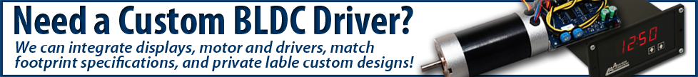
Anaheim Automation also offers an Integrated Motor and Brushless Driver and Controller. This eliminates installation errors and creates a compact, easy-to-use package.
Where is a Brushless Driver and Controller used?
Brushless Drivers and Controllers are used practically everywhere and anywhere you can find a Brushless motor. Some of the industries they appear in, but not limited to, are:
| • Instrumentation |
| • Medical |
| • Appliances |
| • Consumer |
| • Automotive |
| • Industrial Automation Equipment |
| • Aerospace |
| • Military |
What Applications are Brushless Driver and Controller used for?
Some applications brushless driver/controllers are used in are, but not limited to:
| • Appliances |
| ο Wheel encoders |
| ο Ice tray and dust box position sensing |
| ο Door and lid open/close detection |
| ο Low water indicator |
| ο Motor current monitoring and AC input current detection |
| • Automotive (High temperature and in cabin) |
| ο Lighting |
| ο Wiper systems |
| ο Airbag deployment systems |
| ο Brake systems |
| ο Displays and infotainment |
| ο Seat belt systems |
| ο Closure systems |
| • LED lighting and Displays |
| ο Billboards |
| ο Backlighting (cameras, mobile phones, laptop pc's,etc.) |
| ο Illumination and signals |
| • Office Automation |
| ο Printers |
| ο Fax machines |
| ο shredder |
| • Portable |
| ο Digital Camera |
| ο Mobile Phone |
How to select a Brushless Driver and Controller?
When selecting a driver/Controller for your motor, many things should be considered. What is your application? You will need to get specifics about the motor and the driver/controller and compare them to see if they are compatible. Once you have figured all this out, you can then begin to compare driver/controllers from different manufacturers.
Advantages for Brushless Driver and Controller
There are many advantages with Brushless. Such as the following, but not limited to:
| 1. Long lifetime |
| 2. Efficient |
| 3. Customizable |
| 4. Different performance options on one driver/controller |
Disadvantages for Brushless Driver and Controller
There are far more advantages than disadvantages for a Brushless driver/controller, but there are a few listed below:
| 1. High cost |
| 2. Complex circuitry |
| 3. An additional unit to a motor (takes up more space) |
Troubleshooting Brushless Driver and Controller
When you are having problems with your Brushless Driver/ controller there are multiple things to look for. Different units will have their own way of indicating a problem of fault within the driver/controller. Most driver/controllers will have a fault light to help indicate a problem that has occurred. Some may have an "alarm" or noise of some sort.
Some problems that may occur, but are not limited to are:
| 1. Blown phase |
| 2. Improper parts within unit |
| 3. Blown parts within unit |
| 4. Improper wiring/installation (Check user guides for specific hook-up diagrams) |
There is always the possibility that something maybe shorted internally on the board. This is something you might not be able to fix by yourself. Most companies will have a warranty for the product which will allow you to send it back and get it properly fixed and tested.
How much do Brushless Driver and Controller products cost?
Just like everything else, Driver/Controllers have different price ranges. They can be priced as low as a several dollars to as high as several thousands of dollars possibly even more. It just depends how big and complex it is and what options it has, etc. It will also depend on the manufacturer as well.
Physical Properties of a Brushless Driver and Controller
Brushless driver/controllers come in all types of different shapes and sizes. They can be custom made and ordered from different manufacturers. Although there isn't a certain shape it, most driver/controllers have a rectangular or square shape to them. They can also come in very small packages as well as very big packages.
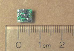
Brushless Motor Driver/Controllers consist of, but are not limited to:
| ◊ PCB (Printed Circuit Board) |
| ◊ Transistors |
| ◊ Capacitors |
| ◊ Resistors |
| ◊ IC, Chips, microchips |
| ◊ Diodes |
| ◊ Potentiometers |
| ◊ Terminal Blocks/ screw terminals |
| ◊ Heat Sinks |
| ◊ LEDs |
| ◊ LCDs |
Formulas for a Brushless Driver and Controller
| ◊ | AC to DC AC (1.414) – 2.8 = DC |
| ◊ | Output Power = (Torque)(No Load Speed) 1351.2 |
| ◊ | Rated Current = Torque (Torque Constant) |
| ◊ | Back EMF Ke = V kRPM |
| ◊ | Setting the Current Limit: The Current of the motor is monitored by the sense resistor. You can monitor this by using an oscilloscope. You will need to calculate the voltage (in milivolts) to set your cursor on your scope. |
Brushless Driver and Controller Glossary
Brushless motor: electric motors powered by direct-current electricity and having electronic commutation systems, rather than mechanical commutators and brushes.
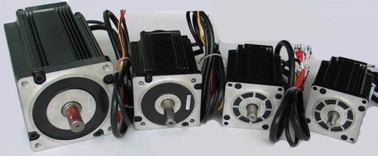
Various Brushless Motors
Capacitor: a passive two-terminal electrical component used to store energy in an electric field.
Controller: takes a signal representing the demanded speed, and drives a motor at that speed.
CL ADJ (Closed-Loop Adjustment): This stands for Closed-loop adjustment. On Anaheim Automation products, you will find a potentiometer labeled CL ADJ, here you can set the speed for closed-loop mode
Closed-Loop: relating to any system in which the output is measured and compared to the input. The output is then adjusted to reach the desired condition. In motion control, the term typically describes a system utilizing a velocity and/or position transducer to generate correction signals in relation to desired parameters.
Commutation: 1. The action of steering currents or voltages to the proper motor phases so as to produce
Diodes: two terminal electronic component with a nonlinear current-voltage characteristic.
Frequency: is the number of occurrences of a repeating event per unit time.
Hall (effect) sensor(s): a transducer that varies its output voltage in response to a magnetic field.
Heat Sink: a term for a component to keep electronic and optoelectronic devices cool.
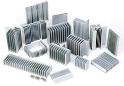
Various Heat Sinks
Inductor: Or also known as a reactor or coil is a passive electrical component used to store energy in a magnetic field. This is measured by inductance, in the units of henries (H).
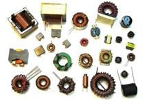
Various Inductors
Integrated Circuit (IC): also referred to as chip or microchip, an electronic circuit manufactured by the patterned diffusion of trace elements into the surface of a thin substrate of semiconductor material.
LCD (Liquid crystal display): a flat panel display, electronic visual display, video display that uses the light modulating properties of liquid crystals.
LED (Light-emitting diode): is a semiconductor light source used as indicator lamps and other lighting.
MOSFET (Metal-Oxide-Semiconductor Field Effect Transistor): A device that can turn very large currents on and off under the control of a low signal level voltage.
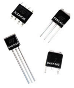
MOSFETS
Open-Loop: a non-feedback controller is a controller type that computes its input into a system using only the current stated and its model of the system
PCB (Printed Circuit Board): used to mechanically support and electrically connect electronic components using conductive pathways, tracks or signal traces etched from copper sheets laminated onto a non-conductive substrate.
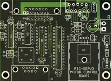
PCB
Phase(s): distribution of alternating current electric power using a system in which all the voltages of the supply vary in unison.
Potentiometer: also referred to as a pot, is a three terminal resistor with a sliding contact that froms an adjustable voltage divider.
PWM (Pulse-width Modulation): or PDM (Pulse-duration Modulation), is a commonly used technique for controlling power to inertial electrical devices, made practical by modern electronic power switches.
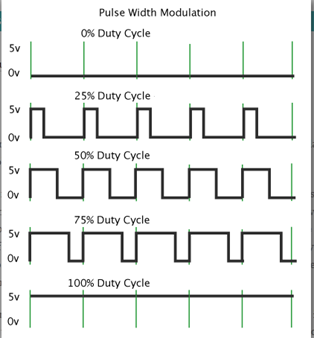
Example of what PWM looks like on an oscilloscope
Resistor: passive two terminal electrical component that implements electrical resistance as a circuit element.
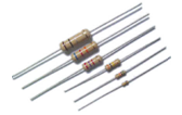
Resistors
Screw Terminal: a type of electrical connector where a wire is clamped down o a metal by a screw.
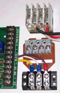
Screw Terminals
Thyristor: a solid-state semiconductor device with four layers of alternating N and P-type materials.
Torque: moment, or moment of force, the tendency of a force to rotate an object about an axis, fulcrum, or pivot.
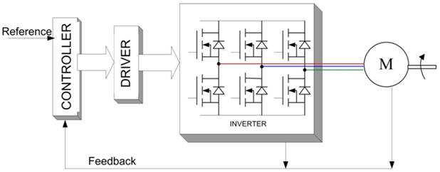
Block Diagram for Systems that use a Brushless Driver/Controller
Lifetime for a Brushless Driver/Controller
The lifetime of a Driver and Controller should last you for a very long time if not almost forever. That's if, and only if you are running within rated conditions. It is not best to run anything at its limits, that's why there are limits set. If you running your unit within or below rate conditions, you will not have to worry too much about checking in on it. It is always a good idea to check on your unit and its conditions. You never know with electronics, they can be unpredictable at times.
Required Maintenance for a Brushless Driver/Controller
Occasionally things go wrong with electronics. You should always make sure the environment of your Driver/Controller is within specifications of the unit so that everything will run smoothly and consistently. The temperature, air, dust, and pressure play a big part in electronics. You always want to make sure those allow your unit to run and operate properly at all times. Those factors are almost always unpredictable and change all the time.
Brushless Driver and Controller FAQ
| 1. | Can different ranges of voltage be applied to the driver/controller? |
| Yes, but keep in mind that there is a minimum and maximum limit of what is inputted. | |
| 2. | Can DC or AC voltages be applied to the driver/controller? |
| Depending on what kind of Driver/Controller you have, it will either take a DC voltage OR an AC voltage, there are a selected few that can take both types of voltages. The user guide will specify. | |
| 3. | Why is the red light on? |
| If the red light is on, that means that there is a fault. The driver/controller is not working properly. You will need to trouble shoot. | |
| 4. | What does PG out mean? |
| On Anaheim Automation driver/controllers PG out stands for Pulse Generator Output. It is a 5V signal pulse out that is available at the rate of 4 pulses for 1 revolution of an 8-polle motor, 3 pulses for 1 revolution of a 6-pole motor, and 2 pulses for 1 revolution of a 4-pole motor. | |
| Helpful Equations: | |
| 1. 8-pole motor RPM = 15 * PG OUT (in Hz) 2. 6-pole motor RPM = 20 * PG OUT (in Hz) 3. 4-pole motor RPM = 30 * PG OUT (in Hz) |
|
| This feature basically allows you to check and monitor the speed of the motor. | |
| 5. | What does the green light mean? |
| The green light means that the driver/controller is powered. | |
| 6. | What is the difference between open loop and close loop? |
| An open-loop controller or a non-feedback controller is a controller type that computes its input into a system using only the current stated and its model of the system. | |
| A closed-loop controller uses a sensor to monitor the system output and feeds the data to a controller which adjusts the speed as necessary to maintain the desired system output. | |
| 7. | Can I hook up multiple motors to one driver? |
| In most cases this is possible, it just depends on what your application is and if the driver/controller will still be able to run within its limits. | |
| 8. | What does the yellow light signify? |
| The yellow light indicates that your motor is running. | |
| 9. | Why isn't my motor running? |
| This can be a number of things. You could have possibly hooked up the motor incorrectly, your input voltage is too low, something internal with the driver/controller, or it may even be the motor itself. Check Trouble shooting section for more details. | |
| 10. | How hot should my driver/controller get? |
| The temperature of the heat sink should never be allowed to rise above 70 degrees Celsius. |
Brushless Driver and Controller Quiz
| 1. | What types of voltages are used to power a Driver and Controller? |
| AC and/or DC. | |
| 2. | How is the speed of the rotor detected? |
| The speed of the rotor is detected by the Hall Effect Sensors. | |
| 3. | How do you set the current limit of the motor? |
| By knowing the current limit value and sense resistor value, solve for the voltage value for scope set up by using ohm's law: V=IR Set scope cursor to voltage value solved for, monitor the sense resistor with scope and set current limit accordingly. |
|
| 4. | What do controllers use to directly measure the rotor's position? |
| Hall effect sensors or rotary encoders, sometimes back EMF | |
| 5. | What is back EMF? |
| Electromotive force refers to voltage generated by the magnetic force according to Farady's law , which states that a time varying magnetic field will induce an electric current. | |
| 6. | What is the difference between closed and open loop control? |
| Closed loop uses feedback to control states or outputs of a dynamical system. Open loop does not use feedback to determine if its output has achieved the desired goal of the input, meaning that they system does not observer the output of the processes it's controlling, so there is no way for it to correct any errors that may occur. | |
| 7. | Other than voltage input, what other inputs may be used to control speed? |
| TTL - CMOS compatible inputs. | |
| 8. | How many hall sensors are present in a Brushless motor? |
| There are 3 Hall sensors. | |
| 9. | How many phases are present in a Brushless motor? |
| There are 3 Phases. | |
| 10. | What is current limiting? |
| Current limiting is the practice in electronic circuits of imposing an upper limit on the current that may be delivered to a load with the purpose of protecting the circuit generating or transmitting the current from harmful effects. It is also a term used in preventing an "overcurrent" in a circuit by opening and clearing the fault in a sub-cycle time frame. |