


What are a Stepper Driver and Controller?
A stepper driver and controller involve electronics and software able to generate the necessary current and pulse sequence to drive a stepper motor. The main function of the hardware and software aspect of a stepper driver and controller is to provide the rated motor phase current to the stepper motor windings in the shortest amount of time. The rate of change of current through the windings is crucial for the stepper motor to run at optimal speed and torque. The resistive force to current change is inductance. In order for current to flow faster, it must overcome the inductive force. The inductive time constant, τ = L/R, plays a vital role in the rate at which current will flow. A low inductive time constant constitutes a faster current flow rate, while a larger inductive time constant will reduce the current flow rate. A stepper driver and controller operate by chopping the input supply voltage. The stepper driver does this by using an embedded pulse width modulation (PWM) chip. Three basic stepper driver and controller categories include L/R, Bilevel and PWM.
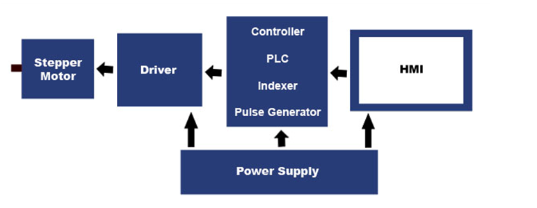
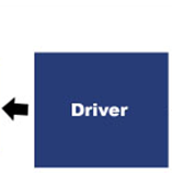
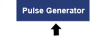
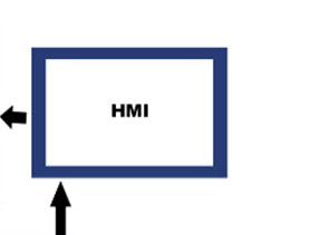
Block Diagram of a Stepper Motor System


How does a Stepper Driver and Controller Work?
The rotor, attached to a metal gear of the stepper motor, is surrounded by electromagnets. The electromagnets also have gear-like teeth which face towards the gears on the rotor but do not come into contact with one another. Once the construction is understood, the motion of the stepper motor is primarily left up to the stepper driver and controller. The stepper driver and controller manage the motor by turning ON the electromagnets individually through pulsed waveforms which travel through the coils to produce electromagnetic fields. This event causes the gears to line up with the first energized electromagnet, but not with the second. Therefore, to turn the stepper motor, the stepper driver turns OFF the first electromagnet and turns ON the second electromagnet. This turns the motor one step. The continuation of this process, from electromagnet to electromagnet, allows the stepper motor to continuously rotate through the control of the stepper driver and controller Stepper motors can take 200 or less steps to make one full revolution. The direction of the motor rotation can be changed by reversing the order of energized electromagnets.
.png)
Basic Types of Stepper Drivers and Controllers
The performance of the stepper motor is highly dependent on the stepper driver circuit. By reversing the stator poles quicker, torque curves may be extended to greater speeds. In order to overcome the inductance and to switch the windings more quickly, the drive voltage must be increased. A stepper driver is divided into three different category types: L/R, Bilevel and Pulse Width Modulation (PWM) stepper drivers.
.png)
L/R Stepper Driver – Resistance Limited
The L/R stepper driver was the basis for older drive designs. This drive technique achieves full and half-step mode operations. Stepper motors driven by an L/R-designed driver do not permit variable control of current levels and produce low to moderate system performance. Therefore, the L/R driver is typically used only as a replacement for older stepper motor systems. The L/R stepper driver is a low-performing driver that provides full rated running torque only at low to moderate speeds, resulting in limited power output. However, the speed and power output may be entirely adequate for some low speed applications. Resistance limited, or L/R stepper drivers, use dropping resistors to match the motor to the power supply. These resistors are usually placed in series with the common leads of the stepper motor. Their resistance should be calculated based on the stepper motor phase current and voltage ratings. The L/R stepper driver circuits are inefficient for applications requiring moderate to high torque and/or speed.
CAUTION: A considerable amount of heat may be generated in resistors which are a part of the circuitry involved (hot enough to burn skin if touched). The required power supply and dropping resistors may be rather bulky; which is another reason a L/R stepper driver is less desirable. These factors must be taken into account before selecting the type of stepper driver to be used with your motor.
NOTE: In more successful L/R stepper driver applications, performance requirements are low enough (i.e. low speed operation) to preclude the need for dropping resistors altogether. In these applications, the stepper motor phase voltages often range from 5 to 35 volts which corresponds to phase currents ranging from low, to very low. These applications make up the bulk of the practical uses for the L/R stepper driver.
.png)
Bilevel Stepper Driver
A bilevel stepper driver uses both high and low voltages. The bilevel stepper driver uses a high voltage to obtain a high rate of current to increase the rise time in the stepper motor windings. When the operating current level is reached, the stepper driver turns off the high voltage and sustains the current level from the low voltage supply, hence the term bilevel. While the stepper motor is stepping, the high voltage drives the current into the windings, supplying more than the required current as the stepping rate increases. This low-high-low voltage switching scheme results in higher efficiency and lower cost than that obtainable from choppers and other more exotic schemes. The bilevel stepper driver eliminates the need for dropping resistors, however it is somewhat more expensive to design and build. Due the growing popularity of the bilevel stepper driver, it is now quite cost-effective overall. Benefits of a bilevel stepper driver is that they do not cause motor heating, nor the RFI and EMI problems associated with chopper type drivers. Anaheim Automation offers a full line of bilevel stepper drivers, from 1 to 10 Amps, model dependent.
NOTE: A bilevel stepper driver can only drive a stepper motor in the half-step or full-step modes. If smoothness is critical to your application, you may need to consider using a microstep driver, or a 0.9 degree stepper motor.
.png)
PWM (Chopper) Stepper Driver/Controller – Microstep
A PWM (pulse width modulation) stepper driver and controller, also referred to as a chopper, constant current, or microstep driver, uses a single high voltage supply. In a PWM stepper driver, stepper motor current is regulated by output transistors switching on and off to achieve an average level of current. There are advantages and disadvantages of stepper driver systems using PWM. The most outstanding feature of PWM drivers is the ability to drive stepper motors in microstep mode. For applications requiring smoothness, the microstep stepper driver is the most suitable option. A microstep driver will maintain constant current rates to the stepper motor at all speeds, offering excellent performance! Typically more costly and complex than L/R and Bilevel stepper driver types, the micro stepper driver features current-boosts and mid-range stabilization, which prove to be essential for many applications. The disadvantages of chopper drives are the production of EMI and RFI, as well as issues with motors overheating. Anaheim Automation offers a full line of "microstep" stepper drivers, from 1 to 10 Amps, model dependent.
Microstepping
Theoretical Microstepping - High microstepping (25,000 - 50,000 steps per revolution) demands quick pulse rates in order to achieve higher speeds. For example, if your microstep resolution is 25,000 steps per resolution, your pulse source must be capable of producing 750,000 pulses per second if it wants to run at a top speed of 1,800 RPM.
TECH TIP: Prior to selecting a step resolution, make sure your pulse generating device can produce step rates high enough to reach the top speed you desire.
The torque available per microstep decreases as the step resolution increases. The following equation explains how the torque available for each microstep is determined:
Torque per microstep = motor holding torque X SIN (90° /microsteps per step).
Example: If the resolution being used is 10,000 steps per revolution with 100 ounce inch motor, then each microstep will generate a torque change of 3.1 oz-in. Increasing the resolution to 50,000 steps per revolution will cause each microstep to produce a torque change of 0.63 oz-in.
If the resolution is 10,000 steps per revolution, with the friction of the load as 3 oz-in, it is expected to get an immediate response to your command to move. Increasing the resolution to 50,000 steps per revolution would take 5 microsteps to be commanded before the torque can build to a level in which it can move the load. This is often called "Empty Stepping," and can be overcome if step resolutions and stepper motor sizes are selected properly.
How to Control a Stepper Driver
A stepper driver and controller is controlled by a DC power supply with associated circuits and software architecture for controlling the switching sequence sent to the stepper motor which causes the shaft to rotate. The circuitry involved not only sends the proper pulse sequence to the motor but also controls speed, direction and the resolution (steps per revolution) of the stepper motor.
How to Select a Stepper Driver
The speed and direction of rotation of a stepper motor is determined by the appropriate configurations of digital control devices. Selecting the most compatible stepper driver and controller and stepper motor can save the user money and be a less cumbersome motion control solution. Anaheim Automation categorizes the major types of digital control devices as follows:
• Stepper Motor Drivers – offered in full-step, half-step and micro-step
• Stepper Motor Controllers (sometimes referred to as Control Links – controllers indexers, and pulse generators sold separately or in Drivers Packs
• Stepper Motor Driver Packs – packaged units that include drivers and optional controller, with a matched power supply (most models are enclosed units that are fan-cooled)
• Integrated Stepper Motor/Driver/Controllers – packaged at the end of a stepper motor are drivers and simple controllers (only available for high-torque stepper motors)
Stepper drivers and controllers provide a method to precisely control speed and positioning. With each pulse converted into digital information, the motor is able to undergo an exact incremental rotation without the need for feedback mechanisms (i.e. tachometers or encoders). With an open-loop system, the problems of feedback loop phase shift and resultant instability, common with servo drives, are eliminated. Before a designer selects a suitable stepper motor and driver and controller combination for an application, there are certain variables which need to be considered. Anaheim Automation offers a full line of bilevel stepper drivers, from 1 to 10 Amps, model dependent, as well as stepper controllers, stepper motors, Driver Packs and integrated stepper motor/driver controller product line.
A machine or process designer must examine several parameters such as load characteristics, performance requirements and mechanical design including coupling techniques for an optimal solution. Failure to do so may result in poor system performance or be more costly than necessary. For optimum stepper driver and controller motion control, the following factors should be taken into consideration:
1. Parameters:
a. Distance to be traversed
b. Maximum time allowed for a traverse
c. Desired detent (static) accuracy
d. Desired dynamic accuracy (overshoot)
e. Time allowed for dynamic accuracy to return to static accuracy specification (settling time)
f. Required step resolution (combination of step size, gearing, and mechanical design)
g. System friction: All mechanical systems exhibit some type of frictional force. When sizing the motor, remember the motor must provide enough torque to overcome any system friction. A small amount of friction is desired since it can reduce settling time and improve performance
h. System inertia: An object's inertia is a measure of its resistance to changes in velocity. The larger the inertial load, the longer it takes a stepper motor to accelerate or decelerate the load. The speed at which the motor rotates is independent of inertia. For rotary motion, inertia is proportional to the mass of the object being moved times the square of its distance from the axis of rotation
i. Speed/Torque characteristics of the motor: Torque (oz-in) is defined as a linear force (ounces) multiplied by a radius (inches). When selecting a stepper driver and motor, the capacity of the motor must exceed the overall requirements of the load. The torque any motor can provide varies with its speed. Individual speed/torque curves should be consulted by the designed for each application
j. Torque-to-Inertia Ratio: This value is defined as a motor's rated torque divided by the rotor's inertia. This ration (measurement) determines how quickly a motor can accelerate and decelerate its own mass. Motors with similar torque ratings can have different torque-to-inertia ratios as a result of varying construction
k. Torque margin: Whenever possible, a stepper driver and controller which can provide more torque than is necessary should be specified. This torque margin allows for mechanical wear, lubricant hardening, and other unexpected friction. Resonance effects can cause the motor's torque to be slightly lower at some speeds. Selecting a stepper driver and motor system that provides at least 50% margin above the minimum required torque is ideal. More than 100% may prove too costly.
2. Calculation: Measurement of inertia, friction and workloads reflected to motor.
a. In an open-loop stepper motor drive system, the motor does not "know" if excessive inertia or friction has made the motor lose or gain one or more steps, thus affecting the position accuracy.
b. Load inertia should be restricted to no more than four times motor rotor inertia for high performance (relatively fast) systems. A low performance system can deliver step accuracy with very high inertia loads, sometimes up to ten times rotor inertia. System friction may enhance performance with high inertia loads
Experimentation: Tailoring
Experimentation for motor sizing is critical due to dynamic changes in system friction and inertia, (load anomalies) which are difficult to calculate. Stepper motor resonance effects can also change when the motor is couple to its load.
Formulas for Stepper Drivers and Controllers
L/R Driver:
L/R Driver Equation for Calculating the Sense Resistor (RS):
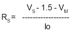
VS = Supply Voltage
VM = Motor Voltage
IO = Stepper Motor Phase Current
L/R Driver Equation to Calculate the Power Rating for the Sense Resistor:
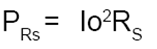
*Note: The Power Rating obtained from this equation should be doubled for the Sense Resistor.
Torque per Microstep = Motor Holding Torque X SIN (90° /Microsteps per Step)
Inductive Time Constant: τ = L / R
Advantages of a Stepper Driver and Controller
• Cost-effective*
• A wide range of rotational speeds can be attained as the speed is proportional to the frequency of the input pulses
• High reliability
• Various stepping resolutions (Smoother motion with microstepping)
*Stepper driver and controller products vary in cost based on the criteria for each application. Some criteria include options of 0.9°, 1.8°, 3.6° and 4.5° step angles, current ranging from .2 to 12.5 Amps and various stepping resolutions. With our friendly customer service and professional application assistance, Anaheim Automation often surpasses customer expectations for fulfilling specific stepper driver and motor requirements, as well as other motion control needs.
Disadvantages of a Stepper Driver
• No feedback to indicate missed steps (unless an encoder is used)
• Cannot accelerate loads very rapidly
• Low output power for size and weight
Stepper Driver and Controller Applications
Anaheim Automation's cost-effective stepper motor, driver and controller product lines are a wise choice for both OEM and user accounts. Anaheim Automation's customers for the stepper motor, driver and controller product lines are diverse: industrial companies operating or designing automated machinery or processes that involve food, cosmetics or medical packaging, labeling or tamper-evident requirements, cut-to-length applications, assembly, conveyor, material handling, robotics, special filming and projection effects, medical diagnostics, inspection and security devices, pump flow control, metal fabrication (CNC machinery), and equipment upgrades. A stepper motor, driver and controller are most often found in motion systems requiring position control.
Anaheim Automation also offers a stepper driver and controller product line that integrates a matched stepper motor into one simple unit. This design concept makes selection easy, thus reducing errors and wiring time. With friendly customer service and professional application assistance, Anaheim Automation often surpasses the customer's expectations for fulfilling specific stepper motor, driver and controller requirements, as well as other motion control needs.
NOTE: Technical assistance regarding the stepper driver and controller product line is available at no charge. This assistance is offered to help the customer in choosing Anaheim Automation products for a specific application. However, any selection, quotation, or application suggestion for a stepper driver and controller, or any other product, offered from Anaheim Automation's staff, its' representatives or distributors, are only to assist the customer. In all cases, determination of fitness of the stepper driver and controller in a specific system application is solely the customers' responsibility. While every effort is made to offer solid advice regarding the stepper driver and controller in a specific application, and to produce technical data and illustrations accurately, such advice and documents are for reference only, and subject to change without notice.
Anaheim Automation is in no event responsible or liable for indirect or consequential damages resulting from the use or application of the stepper driver and controller. Improper use of a stepper driver and controller in an application can result in personal injury or death, property damage, and/or economic loss.
Stepper Drivers and Controllers are used in many Industries
Stepper drivers and controllers have become an essential component to applications in many different industries. The following is a list of industries making use of stepper drivers and controllers:
• Aircraft – In the aircraft industry, stepper motors, drivers and controllers are found in aircraft instrumentations, antenna and sensing applications, and equipment scanning
• Automotive – The automotive industry implements stepper motors, drivers and controllers for applications concerning cruise control, sensing devices, and cameras.
• Chemical – The chemical industry makes use of stepper motors, drivers and controllers for mixing and sampling of materials. They also utilize stepper motor controllers with single and multi-axis stepper motors for equipment testing
• Consumer Electronics and Office Equipment – In the consumer electronics industry, stepper motors, drivers and controllers are found in office equipment such as PC-based scanning equipment, data storage drives, optical disk drive driving mechanisms, printers, and scanners
• Industrial – In the industrial industry, stepper motors are used in automotive gauges, machine tooling with single and multi-axis stepper motor drivers and controllers, and retrofit kits. Stepper drivers and controllers can also be found in CNC machine control
• Medical – In the medical industry, stepper drivers and controllers are utilized in medical scanners, microscopic or nanoscopic motion control of automated devices, dispensing pumps, and chromatograph auto-injectors.
• Scientific Instruments – Scientific equipment implement stepper drivers and controllers to position stepper motors in observatory telescope.
Stepper Driver and Controller Environmental Considerations
The following environmental and safety considerations must be observed during all phases of operation, service and repair of a stepper driver and controller system. Failure to comply with these precautions violates safety standards of design, manufacture and intended use of the stepper motor, driver and controller. Please note that even a well-built stepper driver and controller products operated and installed improperly, can be hazardous. Precaution must be observed by the user with respect to the load and operating environment. The customer is ultimately responsible for the proper selection, installation, and operation of the stepper motor, driver and controller system.
The atmosphere in which a stepper driver and controller is used must be conducive to good general practices of electrical/electronic equipment. Do not operate the stepper driver and controller in the presence of flammable gases, dust, oil, vapor or moisture. For outdoor use, the stepper motor, driver and controller must be protected from the elements by an adequate cover, while still providing adequate air flow and cooling. Moisture may cause an electrical shock hazard and/or induce system breakdown. Due consideration should be given to the avoidance of liquids and vapors of any kind. Contact the factory should your application require specific IP ratings. It is wise to install the stepper motor, driver and controller in an environment which is free from condensation, electrical noise, vibration and shock.
Additionally, it is preferable to work with the stepper driver/motor /controller system in a non-static protective environment. Exposed circuitry should always be properly guarded and/or enclosed to prevent unauthorized human contact with live circuitry. No work should be performed while power is applied to the stepper driver. Don't plug in or unplug the connectors when power is ON. Wait for at least 5 minutes before doing inspection work on the stepper motor, driver and controller after turning power OFF, because even after the power is turned off, there will still be some electrical energy remaining in the capacitors of the internal circuit of the stepper driver.
Plan the installation of the stepper motor, driver and controller in a system design that is free from debris, such as metal debris from cutting, drilling, tapping, and welding, or any other foreign material that could come in contact with circuitry. Failure to prevent debris from entering the stepper motor, driver and controller system can result in damage and/or shock.
Stepper Driver and Controller Mounting
Introduction
Proper installation will achieve the best results from the production capability of the stepper driver and controller system. This can only be accomplished if several important steps are implemented and some precautions are taken. Note: Local codes may suggest different requirements, but those given in this section must be satisfied as much as possible.
Safety First!
Human safety and equipment safety must be the first considerations when performing the installation procedures for the stepper driver and controller system.
CAUTION - Only qualified personnel should be allowed to open and work on the stepper driver and controller, motor, and other components inside electrical enclosures.
Equipment and machinery should never be run unless the electrical enclosure door is closed and locked.
The electronics inside the main electrical enclosure are sensitive to metal chips and filings. During the installation and use of the stepper driver and controller system, great care must be given to make sure metal chips or filings cannot fall onto or into any of the electrical devices.
Electrical Installation
Safety is the number one concern when performing the electrical connection of the stepper driver and controller system, as well as all motion control products and electrical equipment. Therefore, check every step at least once after it has been taken. During the installation of the stepper driver and controller system, it is important to minimize the possibility of electrical noise entering critical sensitive circuits. This is best accomplished by following the electrical installation procedures precisely. Considerable attention has been given to noise immunity in the basic design and manufacture of the stepper motor and stepper driver and controller. However, it is essential that great care and attention be given during the installation of the stepper driver and controller in your machine or in your facility.
Plan Ahead
Before attempting any electrical installations, gather any drawings, instructions or procedural documents you have on the stepper motor, stepper driver and controller, as well as other components in your system. Reading and studying product the stepper motor and the stepper driver and controller documentation before starting the project, will alert you to any special situations, such as the need for specific tools. Also, you will know where to begin and where to go from there. Always keep the specific stepper motor, stepper driver and controller documentation with you while completing the installation, as you should regularly refer to them. Documentation among motor and stepper motor driver and controller manufacturers will vary greatly, as their designs, layouts and connections will not be the same. Carefully match the part numbers of the stepper motor, and stepper driver and controller to the documentation before attempting the installation. Make certain that the stepper motor and the stepper driver and controller are compatible. Even seasoned professionals need guidance and advice while performing complicated electrical installations. This ensures the safest results for everyone.
General Electrical Safety Checklist
When it comes to electronics in the factory or workplace, make sure both the facility and the employees in it are safe at all times. Here is an electrical safety checklist, courtesy of the National Electric Safety Foundation:
Cords and Cables: Make sure cords and cables are in good conditions. Check cords, cables and other wiring for frays and cracks. Make sure that all wiring and cabling is placed out of reach and out of traffic areas. Cords and cables should never be nailed or stapled to the wall, baseboard or to another object. Do not place cords under carpets or rugs. Anaheim Automation recommends using its product-specific cables for its stepper motors, stepper drivers and controller, as well as PCL, PLC, and HMI product lines. Extreme care should be taken if the installer decides to use their own cabling system.
Electrical Plugs and Terminals: Make sure that all plugs fit the outlets. Make certain that the terminals of the stepper motor driver and controller are correctly matched and fit snug. Never remove the ground pin (the third prong) to make a three-prong fit a two-conductor outlet, because it could lead to an electrical shock. Avoid overloading outlets with too many electronic components. Never force a plug into an outlet if it doesn't fit, nor should you ever modify terminal blocks or cables for the stepper driver and controller.
Computer, Controller, HMI, PLC and Drive Products: Check to see that the equipment is in good condition and working properly. Look for cracks or damage in wiring, terminals, plugs and connectors. Use a surge protector bearing the seal of a nationally recognized certification agency.
Lightning: During an electrical storm, make sure you use surge protectors on electronic devices.
The following information is intended as a general guideline for the installation and mounting of the stepper motor, driver and controller system.
WARNING - Dangerous voltages capable of causing injury or death may be present in the stepper motor, driver and controller system. Use extreme caution when handling, testing, and adjusting during installation, set-up, and operation. It is very important that the wiring of the stepper motor, driver and controller be taken into consideration upon installation and mounting.
Subpanels installed inside the enclosure for mounting stepper motor, driver and controller system components, must be a flat, rigid surface that will be free from shock, vibration, moisture, oil, vapors, or dust. Remember that the stepper motor, driver and controller will produce heat during operation; therefore, heat dissipation should be considered in designing the system layout. Size the enclosure so as not to exceed the maximum ambient temperature rating. It is recommended that the stepper driver and controller be mounted in position as to provide adequate airflow. The stepper motor, driver and controller should be mounted in a stable fashion, secured tightly.
NOTE: There should be a minimum of 10mm between the stepper motor, driver and controller along with any other devices mounted in the system/electric panel or cabinet.
NOTE: In order to comply with UL and CE requirements, the stepper motor, driver and controller system must be grounded in a grounded conducive enclosure offering protection as defined in standard EN 60529 (IEC 529) to IP55 such that they are not accessible to the operator or unskilled person. As with any moving part in a system, the stepper motor should be kept out of the reach of the operator. A NEMA 4X enclosure exceeds those requirements providing protection to IP66. To improve the bond between the power rail and the subpanel, construct your subpanel out of zinc-plated (paint-free) steel. Additionally, it is strongly recommended that the stepper driver and controller be protected against electrical noise interferences. Noise from signal wires can cause mechanical vibration and malfunctions.
Anaheim Automation Stepper Driver and Controller Product Line
Anaheim Automation's stepper driver and controller product line is offered in a range of voltages, current and steps per revolution. Customers are impressed with Anaheim Automation's designs, in that they provide outstanding motor performance. Offered in High-Performance Bilevel (Half-Step), Microstep and Line-Powered designs, Anaheim Automation has the most fitting stepper driver and controller for your automation requirements. Taking a system design budget into consideration, Anaheim Automation manufactures its stepper driver and controller products in several packaging styles, making them the most cost-effective choice in the industry!
The stepper driver and controller line offers products that are available in three different inputs (model dependent): 110 VAC or 220 VAC Input, DC Input and AC Input (with transformer). Anaheim Automation manufactures a large variety of stepper driver packs for customers requiring an 110VAC or 220VAC input. These units contain a stepper driver or multiple stepper drivers, with a matched power supply, and are packaged on an open-frame chassis or in an enclosure. Available in one, two, three or four-axis configurations, with bilevel or micro-stepper driver(s) in current ranges of 0.5 to 12.5Amps, with a power supply capacity of up to 800 watts (model dependent). Also included in this product offering is a 10Amp Line-Powered stepper driver. Most popular and typically in stock at all times are the MLA10641 stepper driver and the DPS32001, DPD72001XCE, and DPY50001 stepper Driver Packs.
In the 110VAC and 220VAC Input type stepper driver product line, there are two current ranges to choose from: 2.6-7.0 Amp and the 7.1-12.5 Amp range. Anaheim Automation manufactures a large variety of stepper Driver Packs for customers requiring an 110VAC or 220VAC input. This unit contains a stepper driver with a matched power supply, and is packaged in an enclosure. Available in one, two, three or four-axis configurations, with a bilevel or microstep stepper driver in current ranges of 0.5 to 12.5Amps, with a power supply capacity of up to 800 watts. Also including in this product offering is a 10Amp Line-Powered stepper driver.
A stepper driver can be manufactured by Anaheim Automation for a variety of applications requiring a DC input. This stepper driver product line is offered as single-axis units in open-frame and enclosed modular sheet metal packaging styles. Bilevel, micro-stepper and L/R drive types are available, making them compatible with a wide range of stepper motors. Most popular and typically in stock at all times are the MBC15081, MBC25081TB, MBC05641, MBC12101, and MBC082561 stepper driver products. If the application requires a compact stepper driver for a small stepper motor in the 0-2.5 Amp range, look at stepper driver models such as the MBC158, MBC15081, MBC25081 and MBC25081TB. This series of stepper driver use microstep drive technology. All but the MBC15181 stepper driver is assembled in a small sheet metal package. The low-cost MBC15181 stepper driver model is a printed circuit board style.
If an application requires a stepper driver in the 2.6-7.0Amp range, look at the MBC05641, MBL536, MBL600, M6R7, and the MBD45021-75 models. A stepper driver in this series is modular, meaning they are assembled in small sheet metal enclosures. Featured in this series is the popular divide-by-64 microstep, 1-5Amp stepper driver model MBC05641. A bilevel stepper driver such as the MBL536, MBL600 and L/R-type stepper driver, model M6R7, which are our older "legacy" products are also offered. The MBD45021-75 is an "award winning" specialty stepper driver specifically designed to dramatically enhance torque/speed output in 24 to 40 volt systems.
Anaheim Automation offers a stepper driver that is economical and is designed to cover a wide range of stepper motors. When an application requires a stepper driver in the 7.1-12.5 Amp range, look at the MBC12101, MBC082561, and the BLHP101 stepper driver models. The MBC12101 stepper driver is a fixed divide-by-10 micro-stepper driver with an output capacity of 1.5 to 10 Amps. The MBC082561 stepper driver uses selectable divisors of up to 256 which allows for a very wide range of microstepping options. The older "legacy" high-performance bilevel stepper driver, model BLHP101, is a board-level product more commonly used in electrical panels or other similar enclosures.
A stepper driver manufactured by Anaheim Automation is also available for applications requiring an AC input. These stepper driver models require a transformer (purchased separately), and are available in printed circuit board and modular stepper driver styles. Offered in two current ranges of 2.6 to 7.0Amps and 7.1 to 12.5Amps, these stepper driver models are compatible with a wide range of 4, 6 and 8-lead stepper motors. Some models utilize the bilevel drive technique, which does not create EMI, RFI, and motor heating that is associated with a chopper stepper driver. Also in this product line is the popular micro-stepper driver, MBC10641 that offers eight selectable divisors: 1, 2, 5, 8, 10, 16, 32, and 64. Most popular and typically in stock at all times are the BLD75-1, TM4500, and MBC10641 stepper driver models.
Anaheim Automation manufactures a variety of stepper driver models for customers requiring AC inputs, in the 2.6-7.0 Amp current range. The economical board-level TM4500 and TM4500-80 stepper driver series has an output capacity of 1 to 4.5 Amps. The TM4500-80 doubles the voltages, thus creating better performance at higher speed ranges. The very popular BLD76-1 stepper driver series has an output capacity of 1 to 7 Amps, covering a wide range of stepper motors. The BLD76-1 uses the bilevel drive technique, so it does not create EMI, RFI, or motor heating that is associated with a chopper stepper driver. These stepper driver series require a transformer, which is purchased separately. Additionally, Anaheim Automation's popular and cost-effective MBC10641 stepper driver is perfect for customers requiring AC inputs, operating in current ranges of 1.5 to 10 Amps. This single-axis microstep stepper driver requires a transformer, which is purchased separately. The MBC10641 stepper driver offers eight selectable divisors: 1, 2, 5, 8, 10, 16, 32, and 64. It is compatible with a wide range of 4, 6 and 8-lead stepper motors.
Please Note: If you're looking for matched components for your stepper driver and controller system, look at Anaheim Automation's integrated stepper driver/motor/controller models, or stepper Driver Packs.
Stepper Driver and Controller Wiring
The following information is intended as a general guideline for wiring of the Anaheim Automation stepper motor, driver and controller product lines. Be aware that when you route power and signal wiring on a machine or system, radiated noise from the nearby relays, transformers, and other electronic devices can be introduced into the stepper motor, driver and controller, encoder signals, input/output communications and other sensitive low voltage signals. This can cause systems faults and communication errors.
WARNING - Dangerous voltages capable of causing injury or death may be present in the stepper motor, driver and controller system. Use extreme caution when handling, wiring, testing, and adjusting during installation, set-up and operation. Don't make extreme adjustments or changes to the stepper motor, driver and controller system parameters, which can cause mechanical vibration and result in failure and/or loss. Once the stepper motor, driver and controller are wired, do not run the stepper driver and controller by switching On/Off the power supply directly. Frequent power On/Off switching will cause fast aging of the internal components, which will reduce the lifetime of stepper driver and controller system.
Strictly comply with the following rules:
• Follow the wiring diagram with each stepper motor, driver and controller combination.
NOTE: Manufacturers vary in their color code wiring schemes
• Route high-voltage power cables separately from low-voltage power cables.
• Segregate input power wiring and stepper driver/motor power cables from control wiring and motor feedback cables as they leave the stepper driver and motor. Maintain this separation throughout the wire run.
• Use shielded cable for power wiring and provide a grounded 360 degree clamp termination to the enclosure wall. Allow room on the sub-panel for wire bends.
• Make all cable routes as short as possible.
NOTE: Factory made cables are recommended for use in our stepper motor, driver and controller systems. These cables are purchased separately, and are designed to minimize EMI. These cables are recommended over customer-built cables to optimize system performance and to provide additional safety for the stepper motor, driver and controller system and the user. Helpful links for individual Anaheim Automation products, motor cable and communication cables:
http://www.anaheimautomation.com/products/accessories/cables.php?tID=136&pt=t&cID=36
http://www.anaheimautomation.com/products/accessories/cables.php?tID=137&pt=t&cID=36
http://www.anaheimautomation.com/products/accessories/cables.php?tID=157&pt=t&cID=36
WARNING - To avoid the possibility of electrical shock, perform all mounting and wiring of the stepper driver and controller system prior to applying power. Once power is applied, connection terminals may have voltage present.
High - Temperature Braided Sleeving – General Practices
The life of cables, wires and hoses can be greatly extended with high temperature braided sleeving. Braided sleeving is a protective cover for the vulnerable material of common wires. High temperatures can cause cracks, frays or fires, especially for wires and cables that are used in industrial settings or exposed to outdoor elements. In addition to protecting the wires from high temperatures, braided sleeving can shield wires and cables from abrasions, chemicals, dirt, and even freezing temperatures.
Shielded Motor Cables Cut-to-Length
Motor cable makes hook-up quick and easy. The cable is shielded for added protection. Minimum purchase is 5 feet, and cut in any increment thereafter. Prices are quoted per foot. Note: The 20 gauge cables are intended for very short runs. See our web site:
http://www.anaheimautomation.com/products/accessories/cables.php?tID=137&pt=t&cID=36
Electrical Safety in the Workplace – General Practices
When establishing electrical safety policy in the workplace, here are some points to consider, in part, courtesy of the National Electrical Safety Foundation:
1. Have a good idea of what could go wrong.
2. Use the right tools for the job.
3. Always follow procedures, drawings and other product documentation.
4. Isolate equipment from energy sources.
5. Identify hazards that may be present.
6. Establish approach limitations to machinery and moving parts to minimize hazards.
7. Be sure you are properly trained for the job.
8. Work on the motor, stepper driver and controller, as well as all other Anaheim Automation products and all other electrical equipment only when de-energized.
9. Check and double-check safety regulations and product documentation
10. Treat de-energized equipment as energized until performing a lockout/tagout test (a test used to disable machinery or equipment to prevent the release of potentially hazardous energy while the machine is being serviced)
Why So Many Electrical Safety Requirements
Organizations, such as the Standard for Electrical Safety Requirements for Employee Workplaces, outlines the steps companies must take to be in federal compliance with safety. They include:
1. A safety program with defined responsibilities
2. Calculations for the degree of an arc flash hazard
3. Electrical safety equipment for workers
4. Training for workers
5. Electrical safety tools
6. Electrical safety labels on equipment
An emphasis on safety is largely due to the fear of what an arc flash can do. An arc flash is a short circuit through the air that can happen when conductors can't support the voltage. An arc flash can be as hot as 5,000 F and creates a brilliant flash of light and loud noise. As radiant energy explodes out of the electrical equipment, hot gases and melted metal can endanger human life. This is why there are four separate industry standards or electrical safety requirements in place to protect workers against arc flashes and electrical safety equipment on the market in the form of boots, suits, gloves and more. It is the responsibility of the installer/user of motors and stepper drivers and controllers, and all other Anaheim Automation products, to become familiar with all safety requirements.
Avoid Working With Live Wires
A "live" wire is one that has electricity running through it. If you are installing or repairing anything electrical, always isolate the equipment from the power source. In addition to turning any circuit breakers off, it is always good to test any circuit or conductor before you touch it. This can be done very simply with a hand-held voltage tester. Use this multi-meter every time you must handle something that is potentially live.
Electrical Hazards
The following are the four main hazards involved with the installation of electrical equipment:
1. Electric Shock - An electric shock or burn occurs when an electric current comes into contact with the skin and conducts through the body. If high-voltage electricity runs through the head or chest, death can occur instantly.
2. Arc Flash Burn - An arc flash occurs when a conductive object gets too close to a high voltage, electrified object. This flash can cause intense heat in the surrounding air, possibly causing clothes to catch fire.
3. Arc Blast Impact - When a metal object triggers an arc flash, a subsequent blast can cause hearing loss and concussion. Also, this blast can cause lacerations from flying metal pieces. Falling-Shocks and arc blasts can easily knock a worker off a high platform, such as a ladder or pole.
Surge-Suppression – General Practices
Transient Electromagnetic Interference (EMI) can be generated whenever inductive loads such as relays, solenoids, motor starters, or motors are operated by "hard contacts" such as pushbutton or selector switches. The wiring guidelines are based on the assumption that you guard your system against the effects of transient EMI by using surge-suppressors to suppress transient EMI at its source. Inductive loads switched by solid-state output devices alone do not require surge-suppression. However, inductive loads of ac output modules that are in series or parallel with hard contacts require surge-suppression to protect the module output circuits as well as to suppress transient EMI.
Electrical noise from any source, whether it is the power line, an electrical arc generated in an adjacent machine or process, or crosstalk within the control, is transmitted by conduction, inductive or capacitive coupling, or radiation. It is extremely important to maintain the electrical enclosures and panels, conduits, wiring shields, and machine members at zero potential and to provide a return path to the earth for noise currents so as to effectively shield the sensitive logic from electrical noise.
EMI – Electromagnetic Interference
Electromagnetic Interference is the radiation or induction of electromagnetic noise on a system or machine. Motors in general are a common source of EMI, due to their electromagnetic circuit components. An electromagnetic disturbance which may degrade the performance of equipment (device, system or sub-system), or causes malfunction of the equipment, is called electromagnetic interference (EMI). Motors are potential sources of noise and can generate common-mode currents. EMI can result in degraded system performance and/or data corruption. When it is very strong, it can cause the system to fail completely. EMI can be radiated or conducted comes from magnetic and electrical sources, respectively. In the case of most motors, both radiated and conducted emissions are present.
Causes of EMI – Typical sources of EMI
Industrial – ARC welding, motors, computers, fast-switching digital devices, Integrated Circuits, power cords
Military - Aircraft navigation and equipment
Household – Refrigerators, washers, dryers, dishwashers, electric shavers, personal computers, air-conditioning and heating systems
Susceptible to EMI – Can cause poor functioning and/or damage
Communication receivers, microprocessors, industrial drives and controls, medical devices, household appliances
EMC – Electromagnetic Compatibility
Electromagnetic Compatibility is the practice of monitoring and reducing unwanted EMI. Electromagnetic compatibility is a near-perfect state in which a receptor (device, system, or sub-system) functions well in a common electromagnetic environment, without introducing
intolerable electromagnetic disturbance to any other devices, equipment or systems that share that environment.
IMPORTANT NOTE: EMC performance concerns the complete stepper motor, drive and controller system, as well as all other motion control systems and machinery. Therefore it is the responsibility of the OEM (original equipment manufacturer) to monitor and reduce undesirable EMI, and not of those who supply motion control products. There are often varying regulations on EMC, depending on the purpose of the system and the country it is used or sold.
EMI Reduction Techniques for motors to improve systems EMC performance.
Arcing (sometimes referred to as arc discharge or voltaic arc) is an electrical characteristic where current can flow through the air, or other normally non-conductive materials. You may have seen instances of arcing between two wires, or on the power rails of trains or trams. This is not to be confused with a electrical spark, as an electrical arc is continuous, however they do look similar.
Whilst arcing can be useful, used in both welding and strip lighting, in some cases it can be a source of EMI. For Example: With DC motors, arcing can be common because of the periodic interruption of the current in the rotor windings. This very high-frequency spectra content, which can appear as wideband noise superimposed onto other signals. DC motors also provide paths for common-mode currents through their frames.
Another example of radiated and conducted emissions can come from the driver circuit. A typical H-bridge circuit should ideally provide a constant current to the motor, but this current has fast rise time spikes due to the fast and frequent switching of the current in the driver circuit. Another significant problem is when the motor is located far from the driver, as this creates a fairly large loop area between motor leads and device frame. The radiation potential is a direct function of the loop area; the larger the loop, the larger the emissions.
• Suppress possible emissions at the source point.
• Make the stepper motor, stepper driver and controller, and all other components in the system less susceptible to EMI emissions
• Make the coupling path as inefficient as possible
• Proper Grounding – Single point, multi-point or hybrid grounding depending upon the frequency of the operation
• Shielding – Metal barrier used to suppress coupling of radiated EM energy into the equipment
• Filtering – Filtering techniques are used to suppress conducted interference on Power, Signal, and Control lines.
• Printed Circuit Board (PCB) – Proper design and layout of printed circuit boards from the early design stage is essential to eliminate EMI issues in the future
• Noise Coupling – Conductive coupling through cables, coupling through common impedance, and ground loop coupling techniques are good preventive measures against EMI issues.
Standard Components
The easiest solution is to place a ceramic capacitor between the motor terminals, as close as possible to the motor. This is known as a decoupling capacitor, and reduces EMI by removing some of the high frequency noise signals. The common value used for these decoupling capacitors is between 100pF and 100nF, depending on the size of the motor.
IMPORTANT NOTE: EMC is an important field in electronics with strict regulations, and motors and their circuits are significant sources of EMI. It is therefore essential that engineers take the appropriate actions to reduce EMI improve EMC as much as possible.
Power Line Interference
This section provides basic information that should help achieve a safe, successful and reliable stepper motor and stepper driver and controller installation. It does not cover all possibilities, but does give good basic information and guidance to stepper motor and stepper driver and controller applications, as well as other motion control systems.
Power lines are one of the most troublesome sources of electrical noise. The power lines to which the motion control components are connected, may also supply power to equipment such as arc welders, high current (induction) furnaces, or large horsepower electric motors. Starting or stopping these large consumers of power, or changing the load conditions on them, may cause transient voltages, which may take the form of voltage surges or dips accompanied by high frequency noise superimposed on the incoming voltage waveform. This electrical noise may cause a digital electronic control system to count incorrectly, lose stored data, store incorrect data, or lose axis synchronization.
Power lines in an ungrounded Delta power system are inherently noisy. This system floats with respect to ground and may also cause excessively high voltages to be applied to equipment connected to it. For these reasons, a grounded Wye power system is preferred for supplying power to a computer controlled machine tool or other motion system.
To minimize the effects of power line noise on computer-controlled machine tools or other motion control system components, the power wiring is physically and electrically separated from the logic signal wiring. Also, shielded cables are used for logic signal wiring where appropriate, and an effective common point ground system is provided. Even though these precautions have been taken, power line noise may still be coupled into the logic in extreme cases and cause the control to malfunction as described above.
Possible Solutions
To eliminate stepper driver and controller, HMI, PLC and computer malfunctions that are caused by excessive power line noise, one or more of the following may be necessary:
1. Reduce existing power line noise or install a separate incoming power line to the machine or process.
2. If the only available power source is an ungrounded Delta type, install a Delta-to-Wye
isolation transformer ahead of the control and ground the neutral of the Wye to improve
noise rejection and to better regulate the input voltage to the controls.
3. Install a motor alternator set ahead of the control to isolate it from the incoming power line.
Possible Effects of EMI in a stepper motor, driver and controller system:
• Intermittent disturbances in the stepper drivers and controllers
• Computers and HMIs may falter and loss data, causing to reset/start-up
• Burn-out of sensitive components
• Disturbs the settings and status registers of control equipment
• Less productivity
• The stepper motor, stepper driver and controller do not cause interference with other components in the system or machinery.
• The stepper motor, stepper driver and controller are not susceptible to EMI emissions from other components in the system or machinery.
• The stepper motor, stepper driver and controller do not cause interference within itself.
Qualified Professionals Only
Electrical wiring is complicated and potentially life-threatening if installed incorrectly. Don't attempt to install the motor or stepper driver and controller, or any other Anaheim Automation product, or other electrical equipment, unless you are certain you have received the proper training and education for the task. This is one area of business you can't afford to be frugal about. If you aren't certain about how to perform the stepper motor, driver and controller installation, always hire a qualified electrician/panel builder/integrator. The motor, stepper driver and controller should never be used around water, moisture, dust, or flammable materials. Adherence to proper safety guidelines can save lives and valuable property by preventing electric shock and fires.
Proper Tools
When installing a stepper driver and controller, and any other wiring dealing with any electrical equipment, it is important to use the proper tools. A non-conductive tool will have a rubber grip for you to hold it by. Never use a tool for installation that is solid metal, even if you are wearing gloves and have the power source turned off. There is no such thing as being too cautious when it comes to electrical shock or burns.
Basic Electrical Safety Rule(s)
The OSHA regulation regarding electrical safe practices states two very important basic points. The first is that live parts shall be de-energized before working on or near them. The second point is that even after the exposed parts have been de-energized, they shall still be treated as energized until they are locked out and/or tagged out. That is why the BASIC RULE for electrical safe practices procedure is stated as follows;
ALL ELECTRICAL CIRCUIT CONDUCTORS, BARE OR INSULATED, ARE ASSUMED TO BE ENERGIZED UNTIL PROVEN OTHERWISE. THEY SHALL BE DE-ENERGIZED, LOCKED OUT AND TESTED FOR THE ABSENCE OF VOLTAGE BEFORE WORKING ON THEM OR WORKING NEAR THEM. WORK ON ELECTRICAL CIRCUIT CONDUCTORS MAY ONLY BE PERFORMED BY QUALIFIED PERSONNEL WHO HAVE BEEN AUTHORIZED TO DO THE WORK.
NOTE: For persons unfamiliar with stepper motors and stepper driver and controller products, as well as other motion control components, Anaheim Automation recommends consulting with a systems integrator for all installations.
Troubleshooting a Stepper Driver and Controller
Problem: The stepper motor is not running.
Solution: Double check the motor wiring is correct and the phases are securely fastened in the terminal block pins. In some cases, stalling of a stepper motor causes a large voltage spike that often damages the phase transistors on the stepper driver or controller. Some stepper drivers and controllers are designed to protect themselves from such occurrences. If not, Transient Suppression Devices can be added externally.
Problem: Intermittent or erratic stepper motor or stepper driver/controller function.
Solution: This is the most common cause of failure and one of the most difficult to detect. Start by checking to ensure all connections are tight between the stepper motor and the stepper driver and controllers. Evidence of discoloration at the terminals/connections, may indicate a loose connection. When replacing a stepper motor, stepper driver or driver pack, or controller in a motion control system, and be sure to inspect all terminal blocks and connectors. Check cabling/wiring for accuracy. Stress stepper motor wiring and connections for poor conditions and check with an ohmmeter. Whenever possible, use Anaheim Automation's shielded cables for stepper motor wiring.
Problem: The cable wiring is too long.
Solution: Users should try to keep cable lengths fewer than 25 feet. Applications requiring wiring from to the motor to the driver/controller exceeding 25 feet, please contact the factory for instructions. It is likely that transient voltage protection be required for such applications.
Problem: Driver/Controller is overheating
Solution: It is essential to the overall performance of stepper drivers and controllers to have adequate ventilation and cooling. Not doing so will shorten the lifetime and lower the overall performance of the driver/controller. Installing a fan or using heat sink material can help maintain the temperature of the driver/controller.
Stepper Driver and Controller Glossary
Bifilar Winding – refers to the winding configuration of a stepper motor where each stator pole has a pair of windings; the stepper motor will have either 6 or 8 lead wires, depending on termination. This wiring configuration can be driven from a unipolar or bipolar driver.
Bilevel Stepper Driver – bilevel stepper driver use high voltage to obtain a high rate of current to increase the rise time in the stepper motor windings.
Clock – a pulse generator, which controls the timing of switching circuits that control the speed of the step motor.
Closed-Loop – a system with a feedback type of control, such that the output is used to modify the input.
Controller (Stepper Motor) – a regulating mechanism; essentially a DC power supply plus power switching with associated circuits for controlling the switching in the proper sequence.
Detent Torque – is the holding torque when no current is flowing in the motor. The maximum torque which can be applied to the shaft of an unenergized step motor without causing continuous rotation. The minimal torque present in an unenergized motor. The detent torque of a step motor is typically about 1% of its static energized torque.
Driver (Stepper Motor) – often referred to as a translator, drives a step motor based on pulses from a clock, pulse generator, or computer. Translates the train of pulses and applied power to the appropriate step motor windings.
Dynamic Torque – the torque developed by a motor while stepping at low rates.
L/R Stepper Driver – is the basis for older drive designs. They are referred to as constant voltage drives since they supply either positive or negative voltage to each winding to set step positions.
Maximum Running Torque – the maximum torque load that the motor can drive without missing a step. This typically occurs when the windings are sequentially energized at approximately 5 pps.
Open-Loop – refers to a motion control system where no external sensors are used to provide position or velocity correction signals.
Pole – the part of a magnetic circuit where a magnetic pole is generated either by a permanent magnet or by windings.
Pulse – an electrical signal or voltage of short duration, used in conveying intelligence.
PWM (pulse width modulation) stepper driver – also referred to as a chopper, constant current, or microstep driver, uses a single high voltage supply to control stepper motors.
Rated Torque – the torque-producing capacity of a motor at a given speed. This is the maximum torque the motor can deliver to a load and is usually specified with a torque/speed curve.
Resolution – the smallest positioning increment that can be achieved. It is frequently defined as the number of steps required for a motor's shaft to rotate one complete revolution. The reciprocal of the number of steps per revolution of the motor.
Rotor – the rotating part of the motor (the shaft may be included).
Stator – the stationary magnetic parts of the motor including the windings.
Step – movement of the rotor from one energized position to the next.
Step Angle – the nominal angle through which the shaft of a step motor turns between adjacent step positions. It depends upon the motor and driving sequence (mode of drive).
Step Increment – an indication of step or motion size. Usually this is specified in degrees for a rotary motor and inches or millimeters for a linear motor.
Step (Stepping, Stepper) Motor – a digital actuator, which operates from discrete pulses (input signals) and produces motion in discrete increments. May be a rotary or linear increment.
Step Position – the angular position that the shaft of an unloaded step motor assumes when energized. The step position is not necessarily the same as the detent position.
Torque – a force or couple tending to, or producing, rotation. Common step motor torque units are oz-in, N-m, or mNm.
Train Pulse – a series of spaced pulses.
Lifetime of a Stepper Driver and Controller
The lifetime of a stepper driver and controller may vary in regards to user application. Following the User Manual for proper installation and use can greatly increase the lifetime of the stepper driver and controller.
Required Maintenance of a Stepper Driver and Controller
Maintenance for a Stepper Driver may change depending on wear from user applications. Anaheim Automation's products are back with a one year warranty which offers great assistance for fixing stepper drivers in a timely manner.
How much do Stepper Drivers and Controllers Cost?
Anaheim Automation offers various stepper drivers and controllers with AC or DC input voltage, operating currents and step resolutions to meet your application needs. The prices depend on the type of the stepper driver and controller, but with the help of our experience Sales Team, we will be able to find a stepper driver/controller that best fits your application needs.
Stepper Driver and Controller FAQ's
Q: What is the difference between a closed-loop stepper motor controller and an open-loop stepper motor controller?
A: In an open-loop stepper motor controller, no feedback is going from the motor to the controller. This type of controller is effective when the motor is carrying a constant load at a steady speed. A closed-loop motor controller is more applicable in applications where load or speed varies. In comparison to the closed-loop controller, the open-loop controller lacks complexity and is more affordable.
Q: When should I use microstepping?
A: Microstepping is typically used in applications which require the motor to operate at less than 700 pulses per second.
Stepper Driver Quiz
Which aspects of a stepper motor does a stepper driver/contoller control?A. Pulses sent to the stepper windings
B. Run / Stop
C. Direction
D. Speed
E. All of the Above
A. Microprocessor
B. Timing Logic
C. Toggle Switch
D. All of the above
A. In full-step two phases are on and in half-step only one phase is on.
B. More resonance is evident in half-step
C. More power required for full-step
D. Half-step offers better resolution
• Aircraft
• Automotive
• Chemical
• Consumer Electronics and Office Equipment
• Industrial
• Medical
• Scientific Instruments
A. L/R
B. Chopper
C. Bilevel
D. ASD
A. Counter
B. Encoder
C. Linear Guide
D. Commutator
A. Can accelerate loads rapidly
B. No feedback to indicate missed steps
C. Complex designs
False
Customizing a Stepper Driver and Controller
Anaheim Automation was established in 1966 as a manufacturer of "turnkey" motion control systems. Its' emphasis on R&D has insured the continued introduction of advanced stepper driver, motor and controller products. Today, Anaheim Automation ranks among the leading manufacturers and distributor of motion control products, a position enhanced by its excellent reputation for quality products at competitive prices. The stepper motor, driver and controller product lines are no exception to the company's goal.
Anaheim Automation offers a wide variety of standard stepper motor, driver and controller products. Occasionally, OEM customers with mid to large quantity requirements prefer to have a stepper driver that is custom or modified to meet their exact design or packaging requirements. Sometimes the customization is as simple as mounting dimensions sheet metal, colors, or a label with their name and part number. Other times, a customer might require that a stepper driver meet an ideal specification such as, speed, torque and/or voltage.
Engineers appreciate Anaheim Automation's stepper driver and controller product line can answer their desire for creativity, flexibility and system efficiency. Buyers appreciate the simplicity of the "one-stop shop," and the cost savings of a custom stepper driver design, while engineers are pleased with Anaheim Automation's dedicated involvement in their specific stepper motor, driver and controller system.
Anaheim Automation's standard stepper driver and controller product line is a cost-effective solution, in that they are known for their rugged construction and excellent performance. A considerable size of its sales growth has resulted from dedicated engineering, friendly customer service and professional application assistance, often surpassing the customer's expectations for fulfilling their custom requirements. While a good portion of Anaheim Automation's stepper driver and controller sales involves special, custom, or private-labeling requirements, the company takes pride in its standard stock base located in Anaheim, California, USA. To make customization of a stepper driver affordable, a minimum quantity and/or a Non-Recurring Engineering (NRE) fee is required. Contact the factory for details, should you require a custom stepper driver in your design.
All Sales for a customized or modified stepper driver and controller are Non-Cancelable-Non-Returnable, and a NCNR Agreement must be signed by the customer, per each request. All Sales, including a customized stepper driver, are made pursuant to Anaheim Automation's standard Terms and Conditions, and are in lieu of any other expressed or implied terms, including but not limited to any implied warranties.
Anaheim Automation's customers for the stepper driver and controller product line is diverse: companies operating or designing automated machinery or processes that involve food, cosmetics or medical packaging, labeling or tamper-evident requirements, cut-to-length applications, assembly, conveyor, material handling, robotics, special filming and projection effects, medical diagnostics, inspection and security devices, pump flow control, metal fabrication (CNC machinery), and equipment upgrades. Many OEM customers request that we "private-label" the stepper driver, so that their customers stay loyal to them for servicing, replacements and repairs.
PLEASE NOTE: Technical assistance regarding its stepper driver and motor product lines, as well as all the products manufactured or distributed by Anaheim Automation, is available at no charge. This assistance is offered to help the customer in choosing Anaheim Automation products for a specific application. However, any selection, quotation, or application suggestion for a stepper motor, or any other product, offered from Anaheim Automation's staff, its' representatives or distributors, are only to assist the customer. In all cases, determination of fitness of the custom stepper driver in a specific system design is solely the customers' responsibility. While every effort is made to offer solid advice regarding the stepper driver product line, as well as other motion control products, and to produce technical data and illustrations accurately, such advice and documents are for reference only, and subject to change without notice.
Stepper Driver and Controller Accessories
Take control of your motion requirements with Anaheim Automation's low-cost stepper driver and motor packaged with controllers, indexers or pulse generators. With several options to choose from, you can select the right stepper motor, stepper driver and controller for your project. A stepper driver can be matched with Programmable Stepper Motor Controllers, and include their own software at no additional charge, making it a great package at an economical price. Also offered are stepper driver products matched with Manual Preset Indexers and simple Ramping Pulse Generators.
Additionally, a stepper driver can be affixed to the back side of the stepper motor. Controllers can be added as an option as well. Controllers, indexers and pulse generators can be purchased separately from the stepper driver, as an accessory.
Also available to complete your stepper driver and controller system requirements are a wide range of stepper motors, cables, power supplies, transformers, encoders, brakes, gearboxes, and HMIs, which are purchased separately as or as an "add-on". For details contact Anaheim Automation directly.